
Path difference
The path difference is the path difference (path difference) of two or more coherent waves . The path difference is decisive for the occurrence of interference phenomena .


Conditions for constructive or destructive interference between two waves
If the path difference between two waves of the same wavelength and the same amplitude is exactly half a wavelength (plus any integral multiple of the wavelength), the two partial waves cancel each other out. This weakening of the intensity is called destructive interference :


If it is an integral multiple of the wavelength, the amplitudes of the two partial waves add up. In this case, there is constructive interference :

With values in between there is a partial cancellation.
Relationship with the phase difference
A phase shift in radians and degrees corresponds to a path difference Δs . The phase difference between two waves is responsible for the amplification and cancellation.


- Superposition of two sinusoidal waves with the phase shift of:
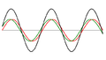
… 20 °

… 170 °

... 180 °


The course of the two individual waves is shown in red and green, their sum is indicated by the black line. The phase difference of 180 ° corresponds to the path difference of half a wavelength (possibly plus integer multiples of the wavelength), which clearly leads to the fact that no amplitude is measured, i.e. a diffraction minimum is present.
Examples: Determination of the path difference in electromagnetic waves
With electromagnetic waves , one typically has to deal with the situation that the absolute path length exceeds the path difference by several orders of magnitude (specifically approx. Half a meter to approx. Half a micrometer, i.e. six powers of ten). Therefore, geometric constructions can always be made with parallel bundles of rays (in contrast to the situation with water waves, for example). With the help of right triangles at points where diffraction occurs on an object, the diffraction angle or the angle of observation can be related to the path difference and the characteristic length (or width) of the diffracting object.
Bragg reflection

In the case of Bragg reflection, the path difference between the rays of two adjacent grating planes is even . Constructive interference between two rays results for , from which the Bragg condition follows.


Diffraction at the single slit

The red arrows show the path difference between individual rays and the upper ray.
The blue sine curve illustrates the field strength of the individual rays along the black line at a point in time chosen as an example. Destructive interference exists for the directions for which entire periods arise here.
If you look at the rays exiting in the direction θ at the individual slit, they have a path difference to each other. The interference pattern results from the fact that the individual rays in direction θ overlap at a distant point (the wall). If the path difference between the beam at the upper end and that at the lower end of the slit is equal to the total intensity measured in this direction, if there is an integer multiple of the wavelength other than zero, since the positive and the Cancel the negative field strengths of the rays in between. A residual intensity remains for all other directions. In the “straight ahead” direction ( k = 0 ), there is a particularly bright maximum intensity, since there all rays are in phase and therefore interfere constructively.

Since we are dealing here with a group of rays, all of which have a path difference compared to the upper ray, the condition for destructive interference deviates from the values mentioned at the beginning, which dealt with the cancellation of two waves. By splitting the beam into two partial beams, one arrives at the following result: The path difference between the two edges is related to the gap width b and the direction angle θ as follows: . This results in minima for the directions θ for which
![\ Delta s \ in [0, D]](https://wikimedia.org/api/rest_v1/media/math/render/svg/42848617c9e8c83af577057c4b20e84248d29864)


- applies.

There is no simple derivation for the maxima.
attachment
supporting documents
- ↑ For a picture of the interference pattern see Gerthsen, section Slit and pinhole diaphragms in the wave optics chapter , ISBN 3-540-16155-4