
Interference (physics)


Interference ( lat. Inter , between 'and ferire over altfrz. S'entreferir , hit each other') describes the change in the amplitude in the superposition of two or more waves after the superposition principle - that is, the correct sign addition of their deflections (not the intensities ) during their penetration. Interference occurs with all types of waves, i.e. with sound , light , matter waves , etc.
In places where the waves cancel each other out, there is destructive interference . In places where they intensify, there is constructive interference . A sign of the occurrence of interference between two wave fields are alternating maxima and minima of the intensity, where each wave field had a uniform intensity. This sequence of constructive and destructive interference is called an interference pattern . A well-known example are the light or dark stripes in the double slit test . The occurrence of interference in the physical experiment is considered proof of the wave nature of the radiation being investigated.
Basics and requirements
coherence

The wave field that arises from the interference of two (or more) waves can only be stable over time if these waves have a (temporally) fixed phase relationship with one another. One then speaks of coherent waves. If the waves are not monochromatic , i.e. consist of a whole series of frequency components, a coherence time is defined, which describes how the waves can be maximally shifted against each other in order to still generate a stable wave field. This coherence time (or the coherence length derived from it ) is an important measure for physical light sources.
Destructive interference
Two waves cancel each other out completely if their deflections are equal in opposite directions at the observed place and time. So that it stays that way for a longer period of time, harmonic (i.e. sinusoidal) waves must have the same frequency and be offset from one another by half an oscillation period or half a wavelength (see phase shift or path difference ). With transverse waves (e.g. light ) the deflections must lie in the same plane, with complex waves (e.g. quantum mechanical wave function ) the complex phase of the amplitude must match.
polarization
Sound waves in solids and electromagnetic waves can be polarized . Investigations into the interference of polarized light led to the realization in 1817 that light waves are transverse waves, see Fresnel-Arago laws . According to this, waves do not interfere if they are polarized perpendicular to one another. However, this only applies to observation with detectors which, like the examples given above, only measure the intensity (proportional to the square of the magnitude of the wave amplitude of the electrical component of the wave).
Mathematical representation
A wave is usually written as a function of place and time . This expresses that a wave propagates both in space and in time. If several waves are superimposed at one place , the wave field can be represented there as a superposition (sum) of the individual waves:


- .

Interference between two waves of the same frequency and amplitude, but different phase
The superposition of two waves with the same frequency and amplitude can be calculated using the trigonometric addition theorems. Become the two waves and with the common frequency , amplitude and phases and through


- and


described, then results for the resulting superposition of the waves
- ,

d. That is, a wave of the same frequency arises, the amplitude of which depends on the difference in the phases of the two original waves and whose phase is the mean of the phases of the original waves.
For equal phases of the waves ( ) the cosine becomes one. The result is an amplitude of , i. That is, the amplitude doubles compared to the output amplitudes, which corresponds to constructive interference.


For a phase difference of 180 ° ( ) the cosine becomes zero, i.e. i.e., the resulting wave disappears. This corresponds to destructive interference .

Interference between two waves of the same frequency but different amplitude and phase
For the same frequency of the waves but different amplitudes and phases, the resulting wave can be calculated using pointer arithmetic. The two waves and have the same frequency , the amplitudes and and the phases and


- and .


The resulting superposition of the waves has the form:

with the amplitude:

and the phase

- .

Superposition of circular waves
Figure 1 shows the interference of two circular wave groups of the same wavelength and amplitude. The crosses mark the position of the sources, the circles the maxima of the respective partial wave. Constructive interference occurs in white areas in a positive direction, and in black constructive interference in a negative direction. There is destructive interference in the gray areas. It can be seen that the minima lie on a cluster of hyperbolas whose focal points are identical to the source locations of the waves. One speaks therefore of a hyperbolic interference with two point sources. The hyperbola is the curve of all points that have the difference in transit time to the two source locations . The vertex distance corresponds to the transit time difference if and represent the time reference of the two feeding time functions and represent the medial speed of propagation.


Figure 2 shows the change in the interference pattern as a function of the wavelength (increases from top to bottom) and as a function of the distance between the sources (increases from left to right). In the dark areas (around the interference minima) there is destructive interference and in the light areas (maxima) constructive interference .
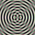
Figure 1: Simulated interference of two circular wave groups of the same wavelength and amplitude

Figure 2: Interference between two circular waves depending on the wavelength and the source distance


Known physical phenomena
There are numerous physical phenomena based on the interference of waves, mostly electromagnetic waves (light). Some well-known examples from different areas are briefly described below.
Beating and standing wave

Superimposing two shafts with dissimilar but close frequencies and so results from the beat a pattern as shown in the lower graph in FIG. 3. A fast oscillation forms ( in brown color), the amplitude of which changes with a slow frequency ( , blue). If intensities are viewed with a detector, then a time averaging over the sampling interval must also be carried out, with the sampling frequency of the detector being.


For normal light sources and frequencies that are so far apart that beating is practically irrelevant, the (time-averaged) interference pattern is the sum of the interference patterns of the individual frequencies. This is based on the fact that the interference between waves with different frequencies - due to the lack of a fixed phase relationship - is omitted in the time averaging. For dichromatic light we get in this case:

where is the Poynting vector .

To tune musical instruments, you can change the corresponding setting until you no longer perceive a beat together with a reference tone (e.g. from a tuning fork). The measurement of beat signals can also be used to measure frequencies that are otherwise too high (for the measuring device). However, this requires a signal source that delivers signals with a very stable and precise frequency.
The interference of two waves of the same wavelength but with opposite directions of propagation leads to a standing wave .
Double slit experiment
With the double slit experiment, Thomas Young provided evidence of the wave nature of light for the first time in 1802. In this experiment, a diaphragm with a double slit is set up in the path of a light beam, the distance between the slits being in the order of magnitude of the wavelength. Behind it there is a screen on which an interference pattern is formed when the light source is sufficiently far from the screen. If only one slit is open and wide enough, the typical diffraction pattern of a single slit is formed . Similarly, the wave character of electrons can be shown with an electron beam; this is discussed in more detail in the section on interference in quantum mechanics (see below).
Interference colors
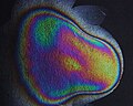
White light, which is reflected on thin layers of optically transparent materials (such as an oil film on water, a thin oxide layer on metals, or simply soap bubbles ) often appears colored. The light that is reflected at the upper and lower interfaces of the thin layer interferes. Depending on the direction, the light of a certain wavelength is then extinguished and only the complementary color to the extinguished light remains.

Interference colors due to an oxide layer on the metal bismuth

Interference colors in broken ice
Interference colors in nail polish layer
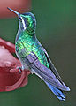
Interference colors in the plumage of the purple-throated nymph

Black precious opal with a full, opalescent play of colors


A well-known example of the appearance of interference colors on two closely adjacent surfaces are Newton's rings . A converging lens with a long focal length rests on a flat glass plate. Around the point of contact, a gap is created between the glass surfaces with a slowly increasing thickness towards the outside. If this arrangement is illuminated with monochromatic light from above, concentric light and dark rings appear around the point of contact between the lens and the glass plate , both in reflection and in transparency. If the experimental setup is illuminated with white light, colored, concentric rings are created. The width of the rings and the intensity of their colors decrease with increasing radius.
The iridescent colors of the opalescence are also a result of interference. In this case, the light of small structures in the interior of the material spread . The colors of many butterflies, some particularly splendidly shimmering birds or the gemstone opal are based on this effect. They are therefore also called structural colors.
White light interference

The superposition of continuously varying wavelength and amplitude (spectrum) creates an interference pattern only within the coherence length . In the white light interferometry this behavior is exploited to obtain a unique length measurement. Another application example can be found in optical coherence tomography , which can thus capture three-dimensional structures.
Laser speckle

The light from an expanded laser beam has almost perfect coherence perpendicular to the beam. This means that laser light is still capable of interference even after being reflected on uneven surfaces. Then every point of the surface serves as a scattering center / point source of a secondary spherical wave. An optical image of these point sources superimposes the light that reaches an image point in different ways in the image. This superposition leads to interference at the pixel. The result depends on the exact length of the light running between the point source and the image point. A path length difference in the size of half the wavelength of the light decides on destructive or constructive interference. Overall, there is a randomly distributed point pattern at the location of the image.
Applications in technology
Anti-noise
In acoustics, destructive interference is used to reduce disturbing noises, so-called anti-noise. This principle comes z. B. used in headphones for aircraft pilots to locally attenuate machine noise.
Interferometer
In the metrology interferometer can be used. These use interference phenomena to measure lengths or phase shifts with very high resolution. To do this, a (light) beam is split into two coherent parts, which are later superimposed again. The two rays cover different distances and back. If these differ by an integral multiple of the wavelength, constructive interference is obtained at the output of the interferometer. If they differ by half a wavelength (phase shift ), destructive interference is obtained. If you now set the interferometer to constructive interference and then introduce an additional phase shift in one of the two arms, you can determine this via the intensity at the output of the interferometer.


There are different implementations of this principle: Mach-Zehnder interferometer , Michelson interferometer , Sagnac interferometer , Fabry-Pérot interferometer, etc.
Radio technology
The direction of observation can be switched very quickly by means of a phase shift between the antenna elements of a phased array antenna . The exact analysis of the phase shifts between the individual antennas of radio telescopes makes it possible to determine the direction of distant radiation sources extremely precisely. An antenna diagram shows the radiation pattern of individual antennas or antenna groups, the shape of which is determined by interference. With the Yagi-Uda antenna , the radiation energy is bundled into a narrow forward lobe, which results in the desired directional effect.
In the balanced duplexer , a gas discharge tube is ignited at high transmission power , which acts almost like a short circuit on the waves. By cleverly distributing energy to two separate branches of a waveguide with different phase shifts and then merging both parts, the transmission energy flows to the antenna (constructive interference) and not to the receiver (destructive interference).
A diplexer enables, through destructive or constructive interference in separate branches of an arrangement of waveguides , that two radio devices of different wavelengths can be operated with one antenna. In a similar way, the sum or difference of two signals of the same frequency is formed in a ring coupler.
Interference in quantum mechanics
Clear explanation

In quantum mechanics , interference phenomena play a decisive role. Particles (and more generally any states of a system) are described by wave functions . These are the solutions to the Schrödinger equation , which can take a form similar to a wave equation . Particles, i.e. matter, can thus behave like waves in quantum mechanics and also interfere (see also wave-particle dualism , matter waves ). A well-known example is the interference of electrons in a double slit experiment (see the pictures on the right) or the interference of two Bose-Einstein condensates .
In 1999, Anton Zeilinger's group succeeded in observing an interference pattern of fullerenes (molecules made up of 60 or 70 carbon atoms). These are by far not the heaviest particles for which quantum interference could be observed. The research group around Markus Arndt continued the experiments initiated by Zeilinger at the University of Vienna and in 2010 was able to show quantum interference with molecules of up to 430 atoms and masses of up to almost 7000 atomic mass units.
What is remarkable about this form of interference, however, is that the measurement of which path a quantum object has chosen (“which path” information) means that only this path is “used” - i.e. no interference occurs. In a double-slit arrangement, the interference pattern depends on whether you can find out which path (through slit 1 or slit 2) the quantum object took. This also applies if the path of the quantum object is not already determined when passing the gap, but only later (delayed measurement process). Only if the “which way” information was never obtained or if it was erased again by a quantum eraser does an interference image emerge behind the double slit.
Mathematical version
In Bra-Ket notation , any quantum mechanical state can be represented in an orthonormal basis ( ). The complex coefficients are:


The probability that a system in the state gives the state when measured is then:


It is important here that not the location probabilities of the particles are superimposed, but the (complex) wave functions themselves. If the location probabilities were superimposed, one would lose the rear interference component in the above formula and the interference pattern would disappear.

De Broglie already postulated at the beginning of the 20th century that all massive particles can be assigned a wavelength , whereby the momentum of the particle is and Planck's quantum of action . With this wavelength one can directly construct the wave function for a particle and thus calculate the interference pattern with the methods described above for light.


See also
literature
- Claude Cohen-Tannoudji , Bernard Diu, Franck Laloë, Joachim Streubel, Jochen Balla: Quantum Mechanics. Volume 1 . 3. Edition. Walter de Gruyter, Berlin / New York 2007, ISBN 3-11-019324-8 .
- Claude Cohen-Tannoudji, Bernard Diu, Franck Laloe: Quantum Mechanics. Volume 2 . 3. Edition. Walter de Gruyter, Berlin / New York 2008, ISBN 3-11-020149-6 .
Web links
- Interactive animations for the interference and superposition of waves
- Graphic solution of overlays
- Simulations with time functions
- Online calculator for interference colors on thin layers
- Lecture Physics III, 59th hour , includes the topic of interference and coherence (University of Tübingen)
- Significance of the interference in audio technology (including graphics)
- Interference of single photons in the interferometer with quantum eraser (QuantumLab)
- Eight basic experiments on interference in the overview ( LEIFI )
- Simulation of the interference between two standing waves
- Animated film about the color of soap bubbles
- Video: Generation and superposition of coherent waves to form interference structures . Institute for Scientific Film (IWF) 2004, made available by the Technical Information Library (TIB), doi : 10.3203 / IWF / C-14880 .
Individual evidence
- ^ RE Allen, HW Fowler, FG Fowler: The Concise Oxford dictionary of current English. Clarendon Press / Oxford University Press, Oxford / New York 1990, ISBN 0-19-861200-1 .
- ↑ BM Rodríguez-Lara and I. Ricardez-Vargas: Interference with polarized light beams: Generation of spatially varying polarization . In: American Journal of Physics. 77, 2009, pp. 1135-1143, arxiv : 0904.0204 .
- ↑ Wolfgang Demtröder: Experimentalphysik 3. Atoms, Molecules and solid bodies . 4th edition. Springer, 2010, ISBN 978-3-642-03911-9 , pp. 366 ( limited preview in Google Book search).
- ↑ Helmut Lindner, Wolfgang Siebke (arr.): Physics for engineers. Specialist book publ. Leipzig im Carl-Hanser-Verl., Munich / Vienna 2006, ISBN 978-3-446-40609-4 , p. 389.
- ↑ Hans Joachim Eichler , Heinz-Detlef Kronfeldt , Jürgen Sahm: The new basic physics internship . Springer, 2006, ISBN 978-3-540-21453-3 , pp. 409 ff . ( limited preview in Google Book search).
- ↑ Katja Bammel: Sound against sound - active noise suppression . In: Physics Journal . tape 6 , no. 2 , 2007, p. 42 ( PDF [accessed May 18, 2014]).
- ^ A. Tonomura, J. Endo, T. Matsuda, T. Kawasaki, H. Ezawa: Demonstration of single ‐ electron buildup of an interference pattern . In: American Journal of Physics . tape 57 , no. 2 , February 1, 1989, p. 117-120 , doi : 10.1119 / 1.16104 .
- ↑ Markus Arndt, Olaf Nairz, Julian Vos-Andreae, Claudia Keller, Gerbrand van der Zouw, Anton Zeilinger: Wave-particle duality of C 60 molecules . In: Nature . tape 401 , no. 6754 , October 14, 1999, p. 680–682 , doi : 10.1038 / 44348 ( PDF [accessed on May 18, 2014]).
- ↑ Björn Brezger, Lucia Hackermüller, Stefan Uttenthaler, Julia Petschinka, Markus Arndt, Anton Zeilinger: Matter-Wave Interferometer for Large Molecules . In: Physical Review Letters . tape 88 , no. 10 , February 26, 2002, p. 100404 , doi : 10.1103 / PhysRevLett.88.100404 .
- ↑ Stefan Gerlich, Sandra Eibenberger, Mathias Tomandl, Stefan Nimmrichter, Klaus Hornberger, Paul J. Fagan, Jens Tüxen, Marcel Mayor, Markus Arndt: Quantum interference of large organic molecules. In: Nature Communications 2, Article 263, doi: 10.1038 / ncomms1263
- ↑ Michael Springer: Wave or Particle - a test with the quantum eraser . In: Spectrum of Science . tape 1 . Spectrum of Science Academic Publishing House, 1996.