
Helmholtz coil

The Helmholtz coil is a special coil arrangement that goes back to the German physicist Hermann von Helmholtz (1821-1894): Two short coils with a large radius R are set up in parallel at a distance R on the same axis and current flows through them in the same direction (in opposite directions Current flow see anti-Helmholtz coil ).
The field of each individual coil is inhomogeneous . The superposition of the two fields results in an area between the two coils near the coil axis with a largely homogeneous magnetic field that is freely accessible for experiments.
There are Helmholtz coils in different designs: cylindrical, square, but also as 3 orthogonally set up pairs (three-dimensional). With the three-dimensional arrangement, one can generate a magnetic field in any direction by varying the current ratio between the coil pairs and thus examine an object without having to rotate it.
properties
In the Helmholtz arrangement, the first, second and third derivatives of the field function disappear in the middle in all directions, while the field strength drops relatively quickly at the edge. The Helmholtz coil is thus the simplest coil arrangement to generate an almost constant magnetic field within a finite volume and is often used in physical experiments. The generated magnetic field strength is - as with every air core coil - strictly linearly dependent on the coil current. The magnetic field strength along the axis can be calculated analytically from the coil geometry, the current and the number of turns. The Helmholtz coil is therefore ideal for calibrating magnetometers.
Distances greater than the coil radius R result in a larger experiment volume, but field strength values that decrease towards the center of the coil. Smaller distances result in greater field strengths, but a smaller experiment volume.
Applications of the Helmholtz coil

- Determination of the specific electron charge according to Helmholtz with a fine beam tube
- Quality control of permanent magnets
- Hall effect -Untersuchungen
- Creation of field-free spaces through targeted shielding of the earth's magnetic field
- Calibration of magnetic field probes and magnetometers
- High frequency coil for magnetic resonance imaging (MRI)
- Gradient coil (Maxwell coil, see below) for MRI
- Magnetic therapy
Calculation of the magnetic flux density

The magnetic flux density of a Helmholtz coil is the sum of the flux densities of the two circular conductor loops . These can be calculated using the Biot-Savart law , but this generally leads to elliptic integrals that cannot be solved analytically . On the axis of symmetry ( z- axis) the field of a single conductor loop centered around


where is the magnetic field constant , the coil radius, the coil current strength and the number of turns per coil. The total field of a coil pair with currents in the same direction and coil spacing is therefore


- .

The flux density in the center of the arrangement at is an even function due to the coil symmetry , which means that all derivatives of odd order vanish there. In particular, the field there is constant in a linear approximation for any coil spacing . The Helmholtz coil is the special case with a maximally homogeneous flux density in the center of the arrangement, in which the second derivative also disappears,


- .

This condition is met for
- ,

so if the distance corresponds exactly to the radius. The field strength then only varies in the fourth order around the center .

The flux density in the center is:

A Helmholtz coil with and generates, for example, a central flux density of .


Inductance
The symmetrical arrangement results in the approach for the two coil parts connected in series . Here is the self-inductance of a single sub-coil. The mutual inductance results from the magnetic coupling of both coil parts to one another and has the same effect on both coil parts.


These are short solenoid coils , which is why the approximate formula applies to the self-inductance
- .

is the length of a solenoid.

The mutual inductance can be calculated for the present arrangement with the Neumann curve integral . After the integration, the formula results
- .

Overall, a Helmholtz coil has the inductance
- .

In the case of an anti-Helmholtz coil , the inductance results from the approach . The mutual inductance has a negative impact on the total inductance, since the magnetic fields are destructively superimposed. So overall:


Variations and further development
Square Helmholtz coil
In practice, the round individual coils are often replaced by square conductor loops with an edge length a . Similar homogeneous fields can thus be generated. The ideal coil spacing is then d = 0.5445 a , somewhat larger than with a round Helmholz coil with diameter a , since the square coil also has a larger area.
Arrangements for even more homogeneous fields

Maxwell coil

Braunbek coil

Barker coil


The area of the homogeneous field is small compared to the overall dimensions of the classic Helmholtz coil. Therefore, many scientists tried to improve the coil arrangement for generating homogeneous fields. These are for example:
- Maxwell coil: three individual coils, whereby the middle coil has a larger diameter and a larger current flows through it
- Braunbek coil: four individual coils, the inner coils having larger diameters. It is an optimized version of the Fanselau coil.
- Barker coil: four individual coils of the same diameter, with the outer coils carrying a larger current
These arrangements improve the ratio between the total size and volume of the homogeneous field and thereby also increase the efficiency because the current paths are shortened. The Barker coil is used in magnetic resonance tomographs , the Braunbek coil in geomagnetic laboratories for the simulation and compensation of the earth's magnetic field and also interplanetary fields, etc. a. for testing spacecraft. Furthermore, spaces free of magnetic fields are created by compensating for external fields, u. a. to magnetometer to test.
Anti-Helmholtz coil
If the current flows through the coils in opposite directions, the field in the center is zero. In the area around the center, the field increases linearly in the axial direction, so that the coil arrangement generates a gradient field. This coil arrangement is called the Maxwell coil , sometimes also called the Anti-Helmholtz coil . The optimal distance d of the individual coils from one another depends on the desired field properties: A maximum field gradient in the center results from the distance , i.e. exactly as with the optimal Helmholtz coil. A gradient that is as homogeneous as possible, in which the second and third derivative of the field strength vanish, arises, on the other hand, with a coil spacing , but with a gradient strength that is approximately 25% lower.

The calculation of the field course along the axis of symmetry ( z- axis) takes place in a completely analogous way as in the case of the same direction of the circular currents. For coil pairs with the same number of turns N one obtains :

With the coil spacing, the following applies to the field gradient in the center:

The following applies to the coil spacing :

Image gallery
Measured or calculated field profiles for Helmholtz coils are shown below:
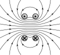
Field lines

Field course in the direction of the coil axis (measured)

Field course transverse to the direction of the coil axis (measured)

Magnetic field of the Helmholtz coil made visible with iron filings

Calculated magnetic field of the Helmholtz coil
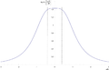
Magnetic flux density along the axis through the center of the coils; z = 0 is the point in the middle between the coils.

Magnitude of the magnetic flux density as a function of the location. The cutting plane goes through the center.

Maxwell coil: Field strength curve with optimized coil distance from and individual fields in arbitrary units.


Web links
Individual evidence
- ↑
- ↑ Carl Heller: About the generation of large-scale, homogeneous magnetic fields for studying the behavior of magnetic compasses and compensation means at different magnetic latitudes . In: German Hydrographic Journal . 8, No. 4, 1955, pp. 157-164. doi : 10.1007 / BF02019812 .
- ↑ James Clerk Maxwell: Treatise on Electricity and Magnetism , Volume 2. The Clarendon Press, Oxford 1873, ISBN 0-486-60636-8 , p. 320.
- ↑ Werner Braunbek: The generation of largely homogeneous magnetic fields by circulating currents . In: Journal of Physics . 88, No. 5-6, 1934, pp. 399-402. doi : 10.1007 / BF01343500 .
- ↑ G. Fanselau: The generation of largely homogeneous magnetic fields by circulating currents . In: Journal of Physics . 54, No. 3-4, 1929, pp. 260-269. doi : 10.1007 / BF01339844 .
- ^ JR Barker: New Coil Systems for the Production of Uniform Magnetic Fields . In: Journal of Scientific Instruments . 26, 1949, pp. 273-275. doi : 10.1088 / 0950-7671 / 26/8/307 .
- ↑ http://www.serviciencia.es/folletos/Braunbek-Barker-Examples-1.pdf Prospectus of the company Serviciencia, SL / Spain, accessed 2017-09-18
- ↑ http://www.igep.tu-bs.de/institut/einrichtungen/magnetsrode/ 3D-Braunbek coil system in Magnetsrode - a geomagnetic laboratory
