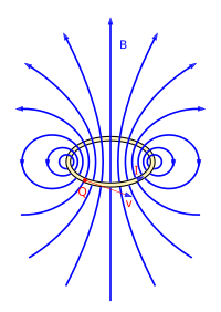
Conductor loop
In electrical engineering, a conductor loop describes an area spanned by a conductor . A distinction is made between a closed and an open conductor loop. It forms the smallest unit of a coil and is used particularly in physics and electrical engineering to illustrate the law of induction .
The magnetic field
A magnetic field is created around every current-carrying conductor. As with the straight wire, each section is surrounded by concentric field lines in the immediate vicinity. If one takes a closed conductor loop through which current flows as a model, the direction of the field lines can be determined using the right-hand rule .
A round conductor loop at the origin around the axis with the radius , through which a current of strength flows, generates the magnetic flux density according to the Biot-Savart law (with cylindrical coordinates )
- .
Here, over the angular once around the conductor loop integrated , said and . This is broken down into components
- With
where and are the complete elliptic integrals of the first and second kind. and are unit vectors of the cylindrical coordinates. For reasons of symmetry, there are neither dependencies nor components in the direction. The above formula for is numerically unstable in the vicinity of , which can be fixed by a Taylor expansion or the use of the Carlson forms .
The flux density is on the symmetry axis of the conductor loop ( ) at a distance from the center point
- .
If several conductor loops are arranged next to one another (coil), the resulting magnetic field is calculated as a superposition of the individual fields. A series of circular conductor loops results in a solenoid .
Lorentz force between two conductor loops
Conductor loops exert Lorentz forces on one another through their magnetic field . The axial force between two coaxially arranged circular conductor loops with radii , and currents , with an axial distance is:
- ,
with and as above. It follows from this, for example, that the attractive axial force is in a Helmholtz coil .
For large distances the force corresponds approximately to a force between two dipoles with dipole moments :
For identical radii and small distances , the force corresponds to that of two parallel conductors:
Induced tension
A voltage is induced in an open conductor loop, which is proportional to the magnetic flux flowing in it . In general, according to the law of induction :
With
Application examples
generator
A generator basically consists of a current-carrying conductor loop that is rotated by mechanical energy in a static, homogeneous magnetic field. In the above formula of the law of induction, the magnetic field is assumed to be constant and only the area is assumed to be changeable over time. Thus one obtains for the magnetic flux
transformer
The basic principle of the transformer can be illustrated by two opposing coils, each made up of several conductor loops and only connected to an iron core that is not electrically conductive. The working mechanism of the transformer is the voltage transformation, in which the area of the conductor loop is assumed to be constant and the magnetic field to be changed over time. The law of induction gives for the magnetic flux
The changing magnetic field is generated in the transformer by applying an alternating voltage and the magnetic flux induces a voltage in the opposite coil via the iron core .
literature
- Heinrich Frohne , Karl-Heinz Locher, Hans Müller: Moeller basics of electrical engineering. Vieweg + Teubner, Stuttgart 2008, ISBN 978-3-8351-0109-8 .
- Karl Küpfmüller , Gerhard Kohn: Theoretical electrical engineering and electronics. Springer, Berlin 1993 (14th edition), ISBN 3-540-56500-0 .
Individual evidence
- ↑ Karl Friedrich Müller: Calculation of the inductance of coils . In: Archives for electrical engineering . 17, No. 3, May 1, 1926, pp. 336-353. ISSN 1432-0487 . doi : 10.1007 / BF01655986 .
- ↑ Kuno Foelsch: Magnetic field and inductance of a cylindrical coil . In: Archives for electrical engineering . 30, No. 3, March 3, 1936, pp. 139-157. ISSN 1432-0487 . doi : 10.1007 / BF01657310 . Eq. (11) and (12)
- ^ Peter Lowell Walstrom: "Algorithms for Computing the Magnetic Field, Vector Potential, and Field Derivatives for Circular Current Loops in Cylindrical Coordinates" . In: "OSTI Technical Report" . August 27, 2017. doi : 10.2172 / 1377379 .
- ^ MW Garrett: Calculation of Fields, Forces, and Mutual Inductances of Current Systems by Elliptic Integrals . In: Journal of Applied Physics . 34, No. 9, September 1963, pp. 2567-2573. doi : 10.1063 / 1.1729771 .


