Transverse rotors
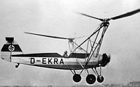
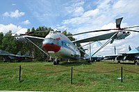
The structural design with transversal rotors is a type of construction for helicopters in which two rotors are arranged side by side on an imaginary line perpendicular to the longitudinal axis ( transversely , ie “across”). By running in opposite directions, the torques acting on the airframe cancel each other out, so that the tail rotor , which is usually used in helicopters, is superfluous.
The Flettner double rotor also works with a transverse rotor arrangement, but with only a small distance between the slightly tilted rotor axes .
development
This construction was at the beginning of the development of the rotary wing aircraft . In the mid-1930s, Henrich Focke and, a little later, Anton Flettner built the first usable samples of this type in Germany: The Focke-Wulf Fw 61 was just a test sample ; the Focke-Achgelis Fa 223 and the Fl 282 reached series production, which, however, was delayed or interrupted by the effects of the war.
After the war, the principle was adopted by manufacturers in different countries. The largest helicopter to date, the Soviet Mil Mi-12 from 1968, also used the transverse rotor design. In the end, however, the principle did not prevail and all models were retired.
It has only recently become important again , for example in convertible aircraft with tilt rotors , such as the Bell Boeing V-22 Osprey .
advantages
- The two laterally arranged rotors, moving in opposite directions in the same plane, result in perfect symmetry without transverse forces. It is also a prerequisite for use in convertible aircraft because it is retained when the rotor plane is tilted forward by up to 90 °.
- The rotors have a smaller diameter than a single rotor helicopter with the same load capacity. You can turn faster with the same blade tip speed with a smaller blade angle of attack , which results in less blade resistance and lower power expenditure . In addition, the leaves can be held more easily.
- Each rotor moves its own amount of air without influencing one another. This also means a lower overall performance compared to tandem or coaxial rotors .
- While with the tail rotor construction up to 15% of the power in hovering operation has to be used for the torque compensation, with transverse rotors the full power is always available for the lift.
disadvantage
- The support frames on both sides result in a relatively high forehead resistance , which affects the achievable airspeed , despite all efforts to cover the truss parts as aerodynamically as possible .
- In order to avoid loss of control travel in the pitch axis as far as possible, with this rotor arrangement, just as with the single-rotor helicopter, only a very small center of gravity is possible and permissible. The distribution of the load in the longitudinal direction must therefore be carried out and monitored very carefully.
- Although no torque is offset, a helicopter of this concept needs nevertheless a equipped with a large lever arm empennage with horizontal stabilizer and vertical tail . They are both necessary for faster forward flight because the lateral rotor arrangement does not give any directional stability. The tail unit effect is also important for the autorotation landing . The tail unit in turn requires additional weight and space.
control
The two Focke helicopters and largely also the Flettner models were controlled as follows:
- Stick movement in the transverse direction causes opposing collective pitch adjustment on the rotors and thus movement around the roll axis.
- By means of control inputs in the longitudinal direction, both rotor planes are inclined in the same direction forwards or backwards (pitch) by cyclic blade adjustment via the swash plate.
- For the rotation around the vertical axis (yaw axis) with the aid of the pedals, the rotor planes incline in opposite directions forwards or backwards via a corresponding cyclic blade adjustment (yaw).
- The first models did not have a dedicated lever for vertical movement; it was controlled by the throttle lever via the rotor speed. In more recent designs, as in other helicopters, the collective pitch control was used to regulate the thrust of the rotors.
The Fw 61 had another lever to switch to the auto-rotation mode. The change to the autorotation state was not reversible, it then had to be landed with autorotation.
In model helicopters, for pitch and yaw control, the motor pod is partly tilted by servos , while roll and pitch are achieved by changing the speed of the electric motors. This saves the mechanically complex swash plates.
Built pattern with side outriggers
- Aerotechnik WGM 21 (4 rotors, quadrocopter )
- Bratuchin Omega G-4
- Cierva W.11 (three rotors, rotating in the same direction)
- Focke-Wulf Fw 61
- Focke-Achgelis Fa 223
- Kamow Ka-22 Wintokryl ( helicopter )
- Landgrave H-2 (1944)
- McDonnell XHJD-1 Whirlaway
- Mil Wed-12
- SNCASE SE 3000 (replica Fa 223)
See also
literature
- Rolf Besser: Technology and History of the Helicopter. From Leonardo da Vinci to the present. Bernard & Graefe, Munich 1982, ISBN 3-7637-5408-3 .
- Kyrill von Gersdorff, Kurt Knobling: helicopter and gyrocopter . Development history of the German rotary wing aircraft from the beginnings to the international community developments (= Die deutsche Luftfahrt. 3). 2nd, supplemented edition. Bernard & Graefe, Koblenz 1985, ISBN 3-7637-5273-0 .
- Steve Coates, Jean-Christophe Carbonel: Helicopters of the Third Reich. Classic Publications, Hersham 2002, ISBN 1-903223-24-5 .


