Coaxial rotor
A coaxial rotor is a helicopter rotor arrangement in which two main rotors rotating in opposite directions are arranged one above the other in an axis of rotation . A tail rotor can be dispensed with as the torques cancel each other out.
use
A model patented in 1910 and built in 1924 was the Spanish Libélula Viblandi .
At the beginning of the development of helicopters, the coaxial system was often used because it was believed to be the most efficient, for example at the Gyroplane Laboratoire in 1933. The majority of the coaxial helicopters produced today come from the Russian manufacturer Kamow , which specializes in this design . Some types are also used in German-speaking countries as "cranes" for precise installations, e.g. B. of masts, antennas or cable car systems. Kamow produces (e) among others
- Kamow Ka-8 "Flying Motorcycle"
- Kamow Ka-10 NATO code name : "Hat"
- Kamow Ka-15 NATO code name: "Hen"
- Kamow Ka-18 NATO code name: "Hog"
- Kamow Ka-20 NATO code name: "Harp"
- Kamow Ka-25 NATO code name: "Hormones"
- Kamow Ka-26 NATO code name: "Hoodlum"
- Kamow Ka-27 NATO code name: "Helix A + D"
- Kamow Ka-28 NATO code name: "Helix"
- Kamow Ka-29 NATO code name: "Helix-B"
- Kamow Ka-31 NATO code name: "Helix"
- Kamow Ka-32 NATO code name: "Helix-C"
- Kamow Ka-37 drone
- Kamow Ka-50 NATO code name: "Hokum A"
- Kamow Ka-50-2 Erdogan
- Kamow Ka-52 alligator
- Kamow Ka-56 Osa / Wasp (one-man mini-helicopter)
- Kamow Ka-92 , concept design of a flying helicopter
- Kamow Ka-115
- Kamow Ka-126
- Kamow Ka-137 drone
- Kamow Ka-226
Recently, the coaxial rotor principle has been attracting greater interest from manufacturers thanks to new types of materials and production options. Sikorsky built the Sikorsky X2 (first flight in 2008). The X2 has an additional thrust propeller at the rear, which enables the aircraft to reach speeds of up to around 460 km / h.
functionality
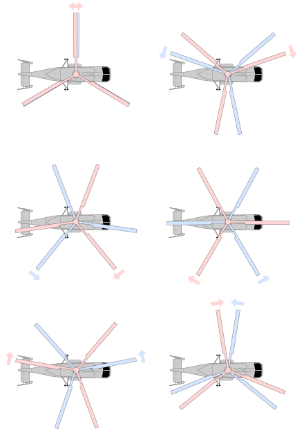
The lower rotor is driven by a hollow shaft, in which the second drive shaft runs to the upper, counter-rotating rotor. The two rotor levels are controlled via control rods to the respective blade holders in order to be able to adjust the angle of attack of the rotor blades during the revolution. The control rods for the upper rotor must be linked by a second swash plate between the rotor planes, which is also actuated by the main swash plate via separate rods, in order to allow for the opposite direction of rotation (see picture of the Kamow Ka-32 in the article). Alternatively, electrical or hydraulic lines can run up in the shaft and control the upper rotor head using servos .
The flight around the pitch and roll axis is controlled by the cyclical blade adjustment (see swash plate ) , as with single rotors . The rotation around the vertical axis ( yaw axis ), however, is achieved by a collective pitch change in opposite directions between the rotors, so that one rotor generates more lift due to a higher angle of attack , which indicates a higher air resistance and thus transfers more (counter) torque to the fuselage and thus creates the desired yaw. Since the other rotor with proportionally less angle of attack generates less counter-torque, drag and also less lift, the total lift is not changed by this type of yaw control and the helicopter largely maintains the flight altitude.
- An advantage of this design compared to the common tail rotor configuration is that no separate torque compensation is necessary because the torques of the two rotors cancel each other out. The counter-torque that is generated in a tail rotor requires drive power which is not available for generating lift and thus payload or service ceiling.
- Furthermore, the range increases for the same reason.
- The system enables a particularly smooth hovering flight, since no drift - a lateral thrust component of the tail rotor that would have to be compensated by means of roll control - occurs (see also drift ).
The full engine power can also be converted into lift.
- The disadvantage of this design is the higher construction and maintenance costs for the two rotor heads with the more complex control of the upper rotor and the gearbox . The spread of the coaxial system is limited by the higher costs (and possibly shorter maintenance intervals).
Model coaxial helicopter
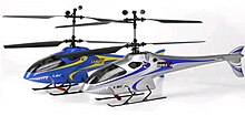
In model helicopters , a simpler variant of the coaxial rotor with a fixed blade angle is used today, since the lack of drift and the high inherent stability facilitate operation in limited space or indoors . About the yaw axis is controlled by the ratio of the speed of the two electronically controlled electric motors , which each drive one of the two rotors rotating in opposite directions.
The upper swashplate can be dispensed with due to the low center of gravity, the large distance between the rotor levels and also because of the use of a stabilizer bar on the upper rotor head; the construction is therefore cost and weight saving.
Other multi-rotor systems
Other helicopter systems with a double rotor are the tandem configuration , transverse rotors and the Flettner double rotor .


