
Folding wing rotor
A folding wing rotor is a simple fluid flow machine ( wind turbine or water turbine ) in which the wings (blades) periodically adjust themselves in a suitable manner during the rotation due to the action of the flow of a fluid (passive adjustment). Rotors with a vertical axis are mostly used (vertical rotors). Top-wing rotors do not have to be turned into the wind. The disadvantage is that the blades shade each other with respect to the flow . Arrangements of the wings in several planes or radially offset are therefore advantageous (see below).


Differentiation from other rotor types
Rotors with active adjustment of the blades are called swivel blade rotors. The best- known example is the Voith-Schneider propeller (vertical axis), in which the blades are pivoted by eccentric control or by coupling gears.
Active blade adjustments are common for wind turbines with a horizontal axis. However, these do not take place periodically during one revolution, but serve to adapt to the wind conditions.
Folding-wing rotors can be built with wing axes that are parallel or approximately parallel to the rotor axis, but also with wing axes that are perpendicular or approximately perpendicular to the rotor axis. The rotors are hybrid rotors, they cannot be clearly differentiated into drag or buoyancy rotors . The circumferential speed of the rotor (movement of the vane axes in relation to the rotor axis) has a strong influence on the drive force ( torque ), since the flaps adjust differently at high circumferential speed due to the higher air resistance that then acts and may be swiveled out of their set position in an uncontrolled manner (they fall " out of step ”). The ratio of peripheral speed and wind speed is called the high speed number (SLZ).
principle
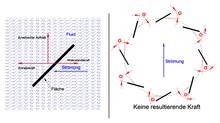
Forces act on a surface (blade, wing) placed at an angle in the flow of a fluid (water, air, etc.) or moved in a fluid at rest. These are the drag or driving force (in the direction of movement) and the dynamic lift (transverse to the direction of flow or movement). A distinction must be made between the drag forces that drive (opposed to the wind) and those that have an inhibiting effect (air resistance in the direction of movement). Both are dependent on the respective flow.
In order to be able to use forces in a rotating machine, inclined surfaces must move on a circular path . However, if the surfaces maintain their angle (relative to the respective tangent ), all forces cancel each other out. It is therefore necessary to change the angle of attack of the surfaces while moving on a circular path. With hinged-wing rotors, this is done by pivoting the surfaces under the action of the fluid.
With the same direction of flow and rotor rotation, the blades adjust themselves in such a way that the flow exerts a force (torque) on the rotor, while in the other case the blades offer the lowest possible resistance to the flow. The rotor is thus driven in a range of rotation of around 180 °, while it is braked in the remaining range. The drive predominates, so that energy can be extracted. The ratio of propulsion and braking is possibly improved by an aerodynamic wing shape ( wing ) or other suitable shapes (including sails ). An extension of the drive range beyond 180 ° is possible through an optimized design of the rotor.
Many different variants of the folding wing rotor have been developed. Some examples are given below.
Rotors with vertical axis and horizontal blade axes

Windmill with a vertical axis and folding blades (1880)

Cardan joints
Cardan joints
animation


Weaver cross
Floor arrangement
Floor arrangement
Frame bracket
A rotor produced around 1880 is shown in the accompanying pictures. Vanes pivotable about the axis AA are attached to the arms connected to the rotor shaft. The wings are connected to a central cardan joint on the shaft via rods and ball joints or cardan joints. Moving one wing inevitably causes movement of all other wings. When there is no wind, all blades are almost equally positioned. When the wind comes up, the wing that is most favorable for the wind direction is raised by the force of the wind (or by its flow resistance ) and the other wings are also pivoted via its linkage and the central universal joint. The rotor begins to turn. The wing, the surface of which is almost perpendicular to the wind direction, is always fully upright and generates the greatest propulsive force (drag). During one rotation of the rotor, each wing swings around its axis from 0 ° to 90 ° and back again.
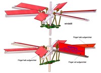
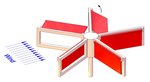
A simple concept was proposed in 1933. Curiously, the same idea was registered for a patent again in 2001. The rotor has four blades, two of which are attached to a common shaft (axes AA and BB) offset by 90 °. Stops limit the swivel range of the sash to 0 ° to 90 °. The wind always erects a wing, whereby the angle of attack of its counterpart inevitably decreases. In the picture, the wing B1 is pressed against its stop, while A1 is moved away from the stop by the wind pressure, with A2 straightening up, also supported by the wind pressure. B2 offers the wind the least possible resistance. In principle, the concept can be implemented with more than two pairs of wings. As mentioned above, the arrangement of one pair of wings in each case in two or more floors is then advantageous. In order to decouple the flows in the individual floors from one another, guide surfaces are useful.
Another example is described in a 2009 patent. The rotor carries several frames from which the blades are hung on hinges. The frames also represent the stops for the sashes. During the forward movement, the sashes come into contact and thus transmit a drive torque. When they return, they are lifted horizontally by the wind pressure and then offer little resistance to the wind.
Rotors with vertical axis and vertical wing axes

Vertical axis with turning wings

Vertical axis with turning wings

Wind engine as drive for a sawmill (Leipzig, 1907)
Rotor with swivel blades

Rotor with rotating blades


Type of wing movement
Reversing wing movement
A folding wing rotor with wing axes parallel to the rotor axis is probably a very old principle. Like weather vanes, the wings are attached to one side of their axes of rotation and aim to align themselves parallel to the wind direction. There are stops for the blades that prevent this alignment, so that a drive torque is transmitted to the rotor by the wind pressure. At the end of the propulsion phase (approx. 180 ° of one revolution) the blades detach themselves from the stops due to the changing direction of the flow, position themselves parallel to the wind direction and now offer the flow the least possible resistance (see animation).
The windmill in the accompanying historical photo worked this way (as far as you can see). It is very similar to the solution already described above (with horizontal axes) in which the leaves are attached to the frame. However, it was realized almost a hundred years earlier. The "invention" registered in 2007 is completely identical to this historical model.
Swiveling wing movement
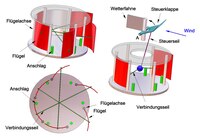
In a rotor is described, the curved wings of which adjust automatically, but do not flip. As with the Weber Cross, two wings are connected, but here by connecting ropes (at different heights for each pair of wings). The wings, which are favorable to the wind, open, while the opposite ones inevitably close against stops. A speed control is provided which reduces the speed in strong winds. In the picture this is shown schematically for two flaps. A weather vane can turn independently of the rotor rotation and adjusts a control flap towards the wind. In strong winds, the normally horizontal control flap is raised. A control rope connected to it pulls the connecting cables upwards so that the open flaps move towards their stops. The driving forces are reduced and the speed is reduced. In the extreme case, all blades are at their stops and no more torque is transmitted to the rotor. The connection of the control cable with the connection cables takes place via rollers in a manner not shown here (symbolized by the ball).
Rotating wing movement
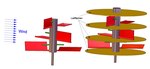
In the rotor described in, the blades perform an orbiting movement while the rotor is rotating.
The rotor carries bearings for the axes of rotation (better: shafts) of the blades on cantilevers. Gear wheels are attached to the axles, which are connected to internal gear wheels via traction means (chains, toothed belts), the diameter of which is half the diameter of the vane gear wheels. The internal gears are firmly connected to the weather vane and designed as a hollow shaft in which the rotor shaft can rotate freely.
The wing movement of a wing during a rotor revolution relative to the wind is shown in the picture. The wing turns 180 ° in the opposite direction during one rotor revolution. This is ensured by the traction mechanism (transmission ratio 2: 1).
The weather vane is always parallel to the wind. The internal gears will then not turn. The vane axes move around the rotor axis, so that the traction means inevitably run onto and off the internal gears and thus rotate the vanes around their axes in the desired manner.
When the wind direction changes, the weather vane and with it the internal gears turn. The wing rotation due to the rotor rotation is thereby superimposed a rotary movement during the pivoting movement of the weather vane, which leads to the fact that after the leveling of the weather vane, the wings move again in an ideal manner to the wind direction.
The rotor described in is a variant of this concept.
The rotor with revolving blades is similar to the Voith-Schneider Propeller (VSP) and, like this, can be used as a drive (and also as a pump / blower). To do this, the weather vane would have to be replaced by a steering device and the rotor shaft driven by a motor. However, in contrast to the VSP, the speed can only be changed by changing the rotor speed.
The example makes it clear that the boundaries between the many rotor types are fluid and that a demarcation is often difficult.
Chinese windmill (Chinese wind turbine)

Artist's impression of a Chinese windmill

Chinese windmill (Chinese wind turbine)

Limitation of wing movement by ropes
Inflow

Torques

The Chinese are credited with an improvement in the rotor principle with folding blades, which was developed a long time ago (probably through trial and error), which makes a drive range of more than 180 ° possible. The fact is used that due to the rotation the effective flow direction of the blades deviates from the wind direction. A further stop assigned to each wing sets the wings for an effective flow during part of the return phase in such a way that lift forces are used for propulsion. It can be assumed that ropes were also used to limit the range of motion of the wings instead of the stops.
The lift forces, like the drag forces, depend on the resulting (effective) flow on the wings and their inclination relative to the tangent to their circular path (angle of incidence). The inflow results from the vectorial addition of the wind speed with the negative peripheral speed of the blades ("airflow" acts against the direction of movement). The flow of air onto the blades is not uniform over their surface, since the leading edge and trailing edge (mostly) do not move on the same radius and thus have different peripheral speeds. As a result, the wind pressure is not evenly distributed over the respective wing surface. This fact is neglected in the following explanations.
The basic arrangement of the stops can be seen in the picture below. The movement of a wing during a rotor revolution is shown. The drive range, in which buoyancy and drag forces act as a driving force, is much larger than 180 °. Forces are transferred to the rotor when the wing rests against one of the two stops. Otherwise, only the (low) air resistance (loss) of the wing placed parallel to the direction of flow acts (in the picture the deviation of the direction of flow from the wind direction is neglected).
A further improvement can be achieved if the wing surface expands asymmetrically on both sides of the wing axis. With the same rotor diameter, the wing area increases, so that there is a greater torque. This wing design corresponds to a junk sail, whose well-known properties may have played a role in the development of the Chinese windmill. The wing (the sail) (like the weather vane) always aligns itself parallel to the effective flow.
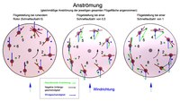
The picture shows the flow for various high-speed numbers. As mentioned above, the higher the speed, the change in the wing position and the drive torque. When the rotor is stationary, the wing changes at position 4, while this is the case for the other two high-speed numbers between positions 3 and 4 or positions 2 and 3. Driving forces are generated in the areas (counterclockwise) between pos. 8 and 5, pos. 1 and 5 and pos. 2 and 5 (wing change not taken into account).
In a further figure, the curves of the drive torques resulting from lift and drag as well as the flow resistance acting in the direction of movement (circular path) for a wing are shown qualitatively (approximately). Exact values are difficult to determine because of the complicated flow conditions (changing lift and drag coefficients , flow separation , eddies, etc.). The high speed number of 0.5 is borderline. It can be seen that the drive torque is mainly generated by the lift, while the drag drive hardly plays a role and sometimes even has a negative (i.e. inhibiting) effect.
Top-wing rotors should be operated with the smallest possible SLZ. With larger SLZ, the air resistance rises sharply, so that the drag drive torque approaches zero and the blades may move in an uncontrolled manner. For example, when the rotor is stationary (SLZ = 0) and the wind direction is perpendicular to it, the greatest driving force caused by the resistance acts on a surface that is radially oriented at 0 °. With an SLZ of 0.5, the surface rushes ahead of the wind at half its speed. The effective wind speed hitting the wing is therefore only half as great. On the opposite side, however, the air resistance in the opposite direction also acts with the same approach flow speed (half the wind speed). There is thus no longer any driving force caused by the resistance. With an even larger SLZ, the wing flips against the wind.
In the case of the Chinese windmill, too, as already explained above, an arrangement of pairs of blades offset by 180 ° in several levels with guide surfaces is advantageous.
It is not known whether modern versions of the Chinese windmill principle were built and tested, so that nothing can be said about the performance. As with the Darrieus rotor and the Savonius rotor , it is advantageous that the generator and, if necessary, the gearbox can be mounted close to the ground, which facilitates installation and maintenance. The large amount of material used (wing bearings, wing surfaces, guide surfaces) is, however, disadvantageous.
Applications
The folding wing rotor has not yet found its place in modern alternative energy generation. Large wind turbines are operated with three-bladed lift rotors with a horizontal axis and smaller ones with Darrieus rotors. Individual enthusiasts try to find application niches (mostly in the private sector) by introducing new variations of the rotor, but so far without much success.
A possibility that has not been considered very much is its use as a water turbine in calm flowing waters (cf. ship mill and power buoy ). There is no need to reckon with constantly changing flow speeds. These are good operating conditions for the folding wing rotor, which is a slow runner. It can be optimized for the respective flow velocity.
The folding wing rotor was only of some importance in the distant past.
Individual evidence
Attention! With DEPATISnet information, an error message often appears the first time it is clicked. The second time the link works.
- ↑ Document DE000000007280A. (PDF) DEPATISnet, accessed on January 3, 2018 .
- ↑ Document DE000001359002U. (PDF) DEPATISnet, accessed on January 3, 2018 .
- ↑ Document WO002003014565A1. (PDF) DEPATISnet, accessed on January 3, 2018 .
- ↑ Document US020090066088A1. (PDF) DEPATISnet, accessed on January 3, 2018 .
- ↑ Document DE000060032430T2. (PDF) DEPATISnet, accessed on January 7, 2018 .
- ↑ Document DE000003526342A1. (PDF) DEPATISnet, accessed on January 13, 2018 .
- ↑ Document EP000000276904A1. (PDF) DEPATISnet, accessed on January 16, 2018 .
- ↑ Document WO002007113401A2. (PDF) DEPATISnet, accessed on January 16, 2018 .