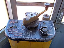
Travel switch
A travel switch is a switching mechanism that is used in electrical drives to control force and speed . The main areas of application are electric locomotives operated with direct current , such as tram cars , locomotives and trolleybuses . Similar switches are also used to control carriers in the mining , of the carousel , cable cars and electric pumps used.
function
The drive switch allows the drive motors of an electric traction vehicle to be operated in different groups and in series or parallel connection. In addition, series resistors can be switched on. The aim is to adapt the tractive force, the acceleration or the driving speed to the requirements. Driving switches were used in particular for DC drives in the medium and low power range. The most important designs are the slip ring travel switch and the cam travel switch.
A slip ring travel switch is equipped with sliding contacts that are attached to a switching drum. Electrically conductive contact fingers access the slip rings from the outside and thus establish electrical contact. By turning the contact roller with the help of a crank, the driver can open and close the contacts and in this way set the desired drive or braking level.
In the case of a cam travel switch , the electrical contacts are located next to the switching drum. Similar to the principle of a music box or a camshaft , cams are attached to the shift drum, which open and close the electrical contacts via small levers. Cam travel switches have the advantage over slip ring travel switches that the sparks that arise during the switching processes can be quickly extinguished in special spark extinguishing chambers, thereby reducing the erosion on the electrical contacts. This is why the cam travel switches increasingly supplanted the slip ring travel switches from the 1920s.
In both cases there is a direction roller for selecting the direction of travel. The direction roller is operated with the attachable direction control key (in German-speaking countries often called "bones" because of its shape). This can only be removed in the zero or neutral position. Driving and direction rollers are mechanically locked against each other. The drive roller can only be moved out of the zero position if the direction roller is laid out, the direction control roller can only be moved in the zero position of the drive roller. Usually there is only one direction control key even in vehicles with two driver's cabs. This prevents both driving switches from being used at the same time.
For higher ratings, one is protecting control used. The large power contactors that switch the motor voltage are controlled either via smaller auxiliary contactors (in the case of electrical contactor control) or via compressed air valves (in the case of pneumatic or electro-pneumatic contactor control).
In the past, the drive switches of trams were placed on the driver's platform, the crank for turning the drive switch was placed directly on the control shaft. Especially in vehicles that were designed to be operated while seated, the crank was replaced by a handwheel with a knob. The finer the gradation of the rear derailleur, the larger and more complex the drive switches became. They were then operated with an intermediate transmission and finally arranged under bench seats behind the driver or under the car floor and operated via cardan shafts . In the past, vehicles for high-voltage AC voltage had similar arrangements, but the actual switchgear was usually located in the separate machine room. Starting resistors are not necessary for AC vehicles, switching between different taps of the main transformer. A direct mechanical connection exists, for example, in German pre-war locomotives with the exception of the E18 series .
From the 1970s onwards, drive switches were largely replaced by modern power electronics such as B. Thyristors replaced in chopper control .
Controller
A controller is used to designate a switching mechanism that is used for speed control and / or current limitation in electric motors . The main areas of application were rail vehicles, see driving switches, and cranes.
The term is derived from the English "to control", which has a meaning that differs from the German "control".
In the elevator industry, the term controller is sometimes used as a synonym for elevator control.
literature
- Ivo Köhler, Tram Manual . Pp. 53-55, GeraMond, 2006. ISBN 3-7654-7142-9
- Günter Boy, Horst Flachmann, Otto Mai: The master's examination in electrical machines and control technology. 4th edition, Vogel Buchverlag, Würzburg, 1983, ISBN 3-8023-0725-9


