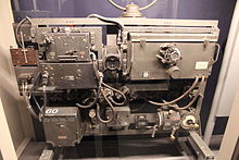
Lorenzbake
Lorenzbake was colloquially called the landing radio beacon (LFF, see also: Lorenz radio navigation and landing systems ) developed by Ernst Ludwig Kramar at the Berlin company C. Lorenz AG in 1932/33 , which is similar to today's instrument landing system (ILS) before an aircraft lands Pilots ( PIC ) supported on final approach . Lorenz set up the first system at Berlin-Tempelhof Airport . Also at Bremen airport , such a system was installed, of which a station in the museum Bremenhalle is issued.
history
In the German Reich of the Weimar Republic from 1931 the Deutsche Luft Hansa tested the ZZ procedure for landings in poor visibility. This first ground-based landing system was time-consuming and required a great deal of effort from the pilot and ground personnel. The airport's direction finding station had to transmit information to the pilot or navigator during the entire approach.
As a result, in the early 1930s, C. Lorenz AG developed an automated process that worked without the help of ground staff. The new "Lorenz Landing System" only offered lateral (lateral) guidance. A representation of the glide path (vertical guidance) had not yet been realized. See also: ILS glide slope transmitter
functionality

The Lorenz Land System consisted of:
- On the ground:
- Control beacon (AFF) - The 120 watt transmitter emitted a beacon pointing in the direction of the runway at a fixed frequency of 33.33 MHz (civil aviation) or a selectable frequency of 30 to 31.5 MHz (air force) which was modulated with a 1150 Hz tone. At an altitude of 200 m, the AFF transmitter could still be received at a distance of 30 km. Corresponds to today's ILS landing course transmitter ("Localizer", LZZ)
- Vor-Einflugzeichen (VEZ) - The 5-watt transmitter, located 3 km from the runway border, emitted straight Morse code with a low tone (400 Hz) at a fixed frequency of 38 MHz. Corresponds to the ILS pre- entry sign ("Outer Marker", OM)
- Main entry sign (HEZ) - The 5-watt transmitter 300 m in front of the runway border also emitted punctiform Morse signals with a higher tone (1700 Hz) vertically upwards at the fixed frequency of 38 MHz. Corresponds to the ILS space entry sign ("Inner Marker", IM)
- The on-board system "FuBl 1" (radio blind landing system, later called realistic radio landing system):
- Beacon receiver "EBl 1" for the control beacon (AFF)
- Entry sign receiver "EBl 2" for the pre- and main entry signs (VEZ and HEZ)
- Converter for generating the anode voltage for the electron tubes in the two receivers
- AFN 1 or AFN 2 (“display device for radio navigation”) in the pilot's field of vision
- Accessories such as antennas as well as relay and switch boxes
use
The next user was the Zurich-Dübendorf airfield and soon the "Lorenz country system" was also in use abroad, including South Africa and Australia. At the end of the 1930s, the German Air Force equipped its air bases and the larger twin-engine machines with Lorenz systems.
Further development of the "knee leg" method
To find the target for the bombers of the German Air Force , Telefunken developed the " Knickebein " method at the beginning of the Second World War . In contrast to the X-procedure , which was first used during the Battle of Britain and required separate on-board equipment, "Knickebein" used the Lorenz radio (blind) landing system "FuBl 1" in the frequency range 30–33 MHz, which was already in the aircraft . For larger target distances later the "FuBl 2" system came with the more sensitive " superheterodyne " -Leitstrahlempfänger type "EBl 3" (instead of the two-circuit - Straight recipient "EBl 1") for installation. Because of the elimination of additional on-board devices that were still required for the X procedure, the radio operators / bombardiers did not need any extensive training for the operation.
The EBl-3 beacon receivers were also used for the " Bernhard " radio navigation system. The rotary radio beacons developed by Telefunken allowed the pilots or navigators / radio operators to determine their own location without sending radio signals or time-consuming and cumbersome cross bearings .
literature
- Fritz Trenkle : On- board radio equipment: from spark transmitter to on-board radar , Volume 7 by Die deutsche Luftfahrt , Bernard & Graefe, 1986, ISBN 978-3-7637-5289-8 , limited preview at www.nonstopsystems.com (PDF; 9.8 MB)
- Brian Johnson: Top Secret: Science and Technology in World War II . Weltbild-Verlag 1994, ISBN 3-89350-818-X
Web links
- 5 watt VHF one-way signal transmitter EZS 2 device manual of the RLM , D. (Luft) T. 4451, February 1941, on: cdvandt.org (PDF, 1.1 MB)
- Control transmitter AS 2 (120 W) device manual of the RLM, D. (Luft) T. 4452, May 1941, on: cdvandt.org (PDF, 6.9 MB)
- Radio landing device Fu Bl 1 device manual of the RLM, D. (Luft) T. 4065, April 1942, on: cdvandt.org (PDF, 5.4 MB)
- Radio landing reception system Fu Bl 1 Ex Description and operating instructions, C. Lorenz AG, On: nonstopsystems.com (PDF, 1.5 MB)
- Radio landing device Fu Bl 2 device manual of the RLM, D. (Luft) T. 4058, February 1943, on: cdvandt.org (PDF, 12.3 MB)

