
M.2


M.2 , formerly known as Next Generation Form Factor ( NGFF ), is a specification for internal computer expansion cards and corresponding ports . The specification was designed to replace mSATA . Due to the smaller and more flexible dimensions in connection with extended functions, M.2 is better suited for connecting SSDs - especially in compact devices such as ultrabooks or tablets . After the failure of SATA Express , M.2 has also established itself in the desktop.
The following three bus systems are supported by the M.2 standard : PCI Express 3.0 , SATA Revision 3.x and USB 3.0 integrated. There are M.2 versions with up to four PCI Express 3.0 lanes (4 × 8 GT / s ), a SATA revision 3.x (6 Gbit / s) and / or a USB 3.0 port (5 Gbit / s) - all via one connection. This allows you to connect both PCI Express and SATA storage via M.2. Both bus systems can also be used in parallel at each port.
Form factors and keys

M.2 cards are rectangular with a connector strip on one side and a semicircular recess for mounting in the middle of the opposite side. Each of the up to 67 pins in 75 possible positions is designed for up to 50 V voltage and 0.5 A current, the connector itself for a maximum of 60 mating cycles. The M.2 standard allows plug-in cards with widths of 12, 16, 22 or 30 mm. The length can be 16, 26, 30, 38, 42, 60, 80 or 110 mm. The M.2 SSDs currently in use are 22 mm wide and 42, 60 or 80 mm long.
An M.2 card is plugged into the appropriate port on a host's circuit board and fixed with a fastening screw. Components can be attached to either side of the card. The card type specifies whether components can be attached on one or both sides and how high the components can be on each side. The maximum permitted height of the components is 1.5 mm. The height of the port can be flat enough to fit on the back of an ATX motherboard or high enough to place two M.2 cards on top of each other. The appropriate fastening screw is usually included with the host board. The screw specifications for thread, length and head type vary depending on the hardware manufacturer. M2x3 screws with a flat head are very often used for fastening (thread diameter 2.0 mm, length 3.0 mm, thread pitch 0.4 mm).
Depending on the intended use of the M.2 card, it has recesses at certain points on the contact edge, the so-called keys. M.2 ports can accommodate modules of one or more keys, depending on which plug-in cards are supported. M.2 modules with cutouts in positions B and M use up to two PCI Express lanes, while M.2 cards, which are only suitable for key M, use up to four PCI Express lanes. Both types also support SATA as a protocol. Despite the keys, attention must be paid to the equipment - that a module fits into a slot does not mean that there is signal compatibility.
| Key ID |
recessed pins |
available interfaces |
|---|---|---|
| A. | 8-15 | PCIe × 2 (with NVMe ), USB , I 2 C , DP × 4 |
| B. | 12-19 | PCIe × 2 (with NVMe), SATA , USB, PCM , UIM , SSIC , UART -I 2 C, SMBus |
| C. | 16-23 | reserved for future variants |
| D. | 20-27 | |
| E. | 24-31 | PCIe (with NVMe), USB, I 2 C, SDIO , UART, PCM |
| F. | 28-35 | reserved for Future Memory Interface (FMI) |
| G | 39-46 | reserved for manufacturer-specific variants (not defined in the M.2 specification) |
| H | 43-50 | reserved for future variants |
| J | 47-54 | |
| K | 51-58 | |
| L. | 55-62 | |
| M. | 59-66 | PCIe × 4 (with NVMe), SATA, SMBus |
| furthermore there are | ||
| A & E | s. O. | PCIe × 2, USB |
| B&M | s. O. | PCIe or SATA |
Pin assignment
| Pin code | Surname | I / O | meaning | Pin code | Surname | I / O | meaning | |
|---|---|---|---|---|---|---|---|---|
| 1 | CONFIG_3 | O | Presence | |||||
| 2 | 3.3V | PI | Power supply | |||||
| 3 | GND | PI | Dimensions | |||||
| 4th | 3.3V | PI | Power supply | |||||
| 5 | GND | PI | Dimensions | |||||
| 6th | POWER_ON_OFF | I. | Switching the module on and off | |||||
| 7th | USB D + | Data for USB 2.0 | ||||||
| 8th | W_DISABLE # | I. | Switching the module on and off via software? | |||||
| 9 | USB D− | Data for USB 2.0 | ||||||
| 10 | LED # or DAS / DSS # | O | ||||||
| 11 | GND | PI | Dimensions | |||||
| 12 | Key B | Notch for M2 key ID B | ||||||
| 13 | Key B | Notch for M2 key ID B | ||||||
| 14th | Key B | Notch for M2 key ID B | ||||||
| 15th | Key B | Notch for M2 key ID B | ||||||
| 16 | Key B | Notch for M2 key ID B | ||||||
| 17th | Key B | Notch for M2 key ID B | ||||||
| 18th | Key B | Notch for M2 key ID B | ||||||
| 19th | Key B | Notch for M2 key ID B | ||||||
| 20th | Res | reserved | ||||||
| 21st | CONFIG_0 | O | GND-WWAN / OC-SSD | |||||
| 22nd | ||||||||
| 23 | WAKE_ON_WWAN # | |||||||
| 24 | ||||||||
| 25th | BodySAR_N | |||||||
| 26th | GPS_DISABLE # | |||||||
| 27 | GND | PI | Dimensions | |||||
| 28 | UIM REF | |||||||
| 29 | ||||||||
| 30th | UIM RESET | O | ||||||
| 31 | ||||||||
| 32 | UIM-CLK | O | ||||||
| 33 | GND | PI | Dimensions | |||||
| 34 | UIM-DATA | IO | ||||||
| 35 | ||||||||
| 36 | UIM-PWR | PO | ||||||
| 37 | ||||||||
| 38 | DEVSLP | Sleep mode | ||||||
| 39 | GND | PI | Dimensions | |||||
| 40 | I2C_SCL | IO | I2C clock | |||||
| 41 | PER0N / SATA B + | |||||||
| 42 | I2C_SDA | IO | I2C data | |||||
| 43 | PER0P / SATA B− | |||||||
| 44 | I2CIRQ | IO | ||||||
| 45 | GND | PI | Dimensions | |||||
| 46 | SYSCLK | O | ||||||
| 47 | PET0N / SATA A− | |||||||
| 48 | TTX_BLANKING | |||||||
| 49 | PET0P / SATA A + | |||||||
| 50 | PERST # | |||||||
| 51 | GND | PI | Dimensions | |||||
| 52 | CLKREQ # | |||||||
| 53 | REFCLKN | |||||||
| 54 | PEWAKE # | |||||||
| 55 | REFCLKP | |||||||
| 56 | ||||||||
| 57 | GND | PI | Dimensions | |||||
| 58 | ||||||||
| 59 | Key M or ANTCTL0 | O | Notch for M2 key ID M | |||||
| 60 | Key M | Notch for M2 key ID M | ||||||
| 61 | Key M or ANTCTL1 | O | Notch for M2 key ID M | |||||
| 62 | Key M | Notch for M2 key ID M | ||||||
| 63 | Key M or ANTCTL2 | O | Notch for M2 key ID M | |||||
| 64 | Key M | Notch for M2 key ID M | ||||||
| 65 | Key M or ANTCTL3 | O | Notch for M2 key ID M | |||||
| 66 | Key M or SIM_DET | Notch for M2-Key-ID M or SIM hot swap detection pin | ||||||
| 67 | RESET # | I. | ||||||
| 68 | SUSCLK | |||||||
| 69 | CONFIG_1 | O | ||||||
| 70 | 3.3V | PI | Power supply | |||||
| 71 | GND | PI | Dimensions | |||||
| 72 | 3.3V | PI | Power supply | |||||
| 73 | GND | PI | Dimensions | |||||
| 74 | 3.3V | PI | Power supply | |||||
| 75 | CONFIG_2 | O | USB 3.0 IND (OC-U3 / GND) | |||||
photos
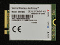
An LTE module in M.2 format

Two SSDs, left: mSATA (mini-SATA), right: M.2


Individual evidence
- ↑ Everything you need to know about M.2. Hardware bulkheads, accessed July 4, 2014 .
- ↑ Volker Rißka: Instead of SATA Express now M2 support for Intel chipsets. Accessed August 21, 2020 .
- ↑ a b c All About M.2 SSDs. SATA-IO, accessed July 4, 2014 .
- ↑ Kent Smith: M.2: Is this the Prince of SSD form factors? lsi.com, accessed July 4, 2014 .
- ↑ PCI Express M.2 Specification, Revision 1.0 (PDF) PCI-SIG . November 1, 2013. Accessed June 13, 2020.
- ↑ M.2 Connector (NGFF) Introduction (PDF) ATTEND. Archived from the original on February 3, 2014. Retrieved January 17, 2014.
- ↑ a b c SMBus interface for SSD Socket 2 and Socket 3 (PCI-SIG engineering change notice) (PDF) PCI-SIG . August 11, 2014. Retrieved August 5, 2015.
- ↑ M.2 SSD Guide - PCIe, NVMe and Co. explained . Retrieved May 8, 2020.
Web links
- M.2 (NGFF) Quick Reference Guide (PDF) Tyco Electronics. Retrieved November 16, 2013.