Plasma fusion cutting
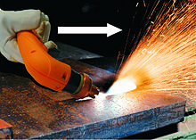
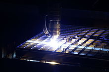
The plasma arc cutting or short plasma cutting is a manufacturing process from the group of thermal separation , which is used for cutting sheet metal. This requires a plasma power source , a plasma torch and other peripheral components (cooling, gas control, guidance system, etc.).
Plasma cutting uses the heat content of a plasma to liquefy the local material and the high kinetic energy of the plasma gas volume flow to blow out the liquefied material. The separable sheet thicknesses are approximately between 0.5 mm and 160 mm.
origin
The technology of plasma cutting developed from plasma welding . Plasma cutting was developed in order to be able to cut metallic materials such as high-alloy steel, aluminum and copper that are not suitable for flame cutting. However, due to its high cutting speeds, the process also established itself in areas of application that were previously reserved for oxy-fuel cutting .
The essential fundamentals of the technology and the first industrially mature system were developed at Kjellberg Finsterwalde . The first plasma fine-jet torch based on argon-hydrogen was built in 1962 by Manfred von Ardenne in collaboration with the company and patented in 1965. In this process, the additional constriction of the plasma jet by means of a secondary medium (for example gas) improves the angular deviation compared to conventional plasma cutting with a focus on the nozzle diameter. In this way, the inclined cut surfaces typical of the process could be avoided. In 1973, Kjellberg operated a plasma cutting machine with inexpensive oxygen for the first time.
Various process variants have been developed to date. In addition to metallic materials, non-conductive materials such as carbides can now also be cut. Plasma cutting is one of the most important cutting processes in industry, as it enables flexible use in 2D and 3D cutting. It is used to prepare edge shapes for the downstream welding process (seam preparation). By cutting with an angled plasma torch, V, Y or K seam shapes can be produced.
functionality
With plasma cutting, a low-energy arc (pilot or auxiliary arc ) is always ignited between the cathode and the nozzle using high voltage. The task of this arc is to partially ionize the gas path between the cathode ( electrode ) and the workpiece ( anode ) - an electrically conductive gas is created ( plasma ). After the pilot arc touches the workpiece, the current is transferred to the workpiece and the power is automatically increased. The main arc is created as the actual cutting arc.
Plasma cutting can be divided into two process principles:
- When plasma cutting with a `` transferred arc '', the arc burns between the cathode (non-melting electrode) and the workpiece (anode). This principle is also known as '' direct plasma cutting '' .
- When plasma cutting with a `` non-transmitted arc '', the arc burns between the cathode (non-melting electrode) and the nozzle (anode) or an auxiliary / sacrificial anode (e.g. melting wire). These principles belong to '' indirect plasma cutting '' .
Direct plasma cutting is mainly used. Plasma marking and plasma grouting complement the application possibilities of this process principle.
Process principle: direct plasma cutting
With direct plasma cutting (see illustration), the power of the plasma power source automatically increases as soon as the pilot arc touches the workpiece and current flows. The main arc burns from the cathode through a gas or water-cooled nozzle, where it is strongly constricted, to the workpiece. The constriction of the approx. 30,000 ° C hot arc generates both the energy density and the high exit speed of the plasma jet. Depending on the material, workpiece thicknesses from 0.5 mm to 160 mm can be cut.
So that there are little or no changes in the cutting current when the plasma arc changes in length, steeply falling characteristics or constant current characteristics are used for plasma cutting .
- Process variants
There are different process variants for direct plasma cutting. They differ in the cutting speed, the material thickness that can be cut and the cutting quality that can be achieved. The current strength, the current density of the plasma arc and the material to be cut have a major influence.
- Conventional plasma cutting: This is the simplest form of plasma cutting. It is often also referred to as air or air plasma, since air is used as the plasma gas. The plasma arc is only bundled by the inner diameter of the plasma nozzle. The arc shape creates a characteristic V-shaped kerf. Today this variant is mainly used for manual and mechanized cutting, jointing and removal. Since simple plasma technology is used, no high quality requirements can be placed on the cut surfaces. The cut edges are usually slightly angled and the surfaces are often rough and coated with a dark oxide layer.
- Plasma cutting with a secondary medium : Using a secondary medium, a defined atmosphere can be created around the plasma arc and the arc can also be constricted. This not only makes the plasma jet narrower and more energetic, but also considerably reduces the original V-shape of the kerf. In addition, the cutting quality improves and the cutting speed can be increased. The cut edges show only a slight angular deviation. Secondary gas or secondary water (in the form of spray mist) are used as media.
- Plasma cutting with water injection: In this process variant, the plasma arc is constricted not only by the nozzle but also by circular, mostly tangentially supplied water (water jacket). It is fed forward along the nozzle and cools it before it is injected. Part of the injection water is split up in gaseous form, the rest of the water is released in liquid form. The cooling effect of the water has an advantageous effect against deformation of the workpiece. In addition, the oxidation on the cut surfaces is reduced. The disadvantage of this method is that very different angular deviations of the two cut flanks occur and only one cut surface meets the quality requirements.
- Plasma cutting with increased constriction effect: This high-precision plasma cutting process has established itself in the industry and is the most common process variant, as it is characterized by high cutting quality and productivity. The increased constriction and the associated concentration of the current density are achieved through highly developed nozzle systems. Special nozzles and gas supply systems generate rotations in the gas (plasma and secondary gas), which can influence the plasma jet. Multi-stage nozzles, some of which discharge gas, are also used. The advantage is that in the range of 0.5 mm to 50 mm material thickness, almost right-angled cuts can be made with increased precision of the molded part. It can cut materials up to 160 mm thick. Usually, oxygen (O2) is used for structural steel and argon-hydrogen mixtures (Ar / H2) or nitrogen (N2) for stainless steel and aluminum.
- Plasma cutting under water cover : In addition to dry cutting , the individual process variants are also partially suitable for cutting on or even under water. With underwater plasma cutting, the secondary medium ensures, in addition to the constriction, that the plasma jet is shielded from the surrounding water bath. In addition, noise, radiation and dust pollution as well as material distortion are reduced. A smoke evacuation system near the burner is still necessary, because water is only able to absorb gases to a limited extent. Solid substances are retained in the water and sink to the bottom of the water basin. Furthermore, the intensity of the visible and UV radiation is reduced. With the same material thickness, this process physically requires a higher amount of energy due to the cooling effect of the water than with dry plasma cutting. This rapid cooling is also visible in the cutting result: the cut surfaces are significantly more grooved / rougher than with dry cutting. The low heat distortion of the components, the formation of a narrow heat-affected zone and almost oxide-free cut surfaces are advantageous, since the workpiece is shielded from the atmosphere. The process is rarely used, however, because with dry or high-precision plasma cutting, significantly smoother cut surfaces are achieved, the handling of components in a water basin is limited and the parts first have to be dried for further processing.
Marking, punching and notching with plasma
Modern plasma cutting systems have a marking function . Line width and penetration depth of this marking can vary, because it depends on the marking current, the marking speed and the gas. If markings on the material can no longer be seen after surface treatment (grinding, painting), the markings are made with light annealing colors that cannot be felt.
In the case of grains (e.g. for later drilling), the plasma jet remains in one place over the material for some time. The marking is no longer just superficial, but noticeably deeper. Functions similarly also the notches is, except that in this case material is removed (higher penetration). Notches are advantageous if they should still be seen as orientation or marking points after the surface treatment.
Plasma joints
With plasma, sheet metal can not only be marked superficially, but also removed deeper. With plasma joints , the torch is slightly inclined, piercing ( i.e. in the direction of movement) so that the melt is driven in front of the arc and blown away.
With this method (faulty) weld seams can be grooved or material defects such as voids, cracks and inclusions can be removed. It is advantageous that the process can be easily observed by the operator and, in contrast to joining with carbon electrodes, it is quieter and less smoke-free. Furthermore, there is no risk of carburization of the workpiece edges. The grouted area can then be welded again immediately or processed in some other way.
Process principle: indirect plasma cutting
In contrast to direct plasma cutting, in indirect plasma cutting the arc does not burn between the cathode and the workpiece, but between the cathode and the nozzle or an auxiliary / sacrificial anode. Since the process works independently of the workpiece, electrically non-conductive materials can also be cut.
- Process variants
The individual process variants differ in their respective anode:
- Nozzle as anode: In this variant, the arc burns between the cathode (electrode) and the nozzle of the plasma torch. The plasma gases are mainly non-oxidizing gases such. B. argon-hydrogen mixtures are used. Mainly electrically non-conductive materials, such as. B. glass fiber reinforced plastics and textiles cut.
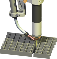
- Auxiliary anode: A wire is used as the anode. In the simplest case this is a welding wire. This is continuously fed into the cutting process, similar to welding, and melts with the cutting process. The great advantage of the process is that the plasma torches can be operated with the same high electrical power as with direct plasma cutting. Both material combinations and interrupted workpieces can be cut without restarting the arc. With the help of the wire, the plasma arc can be shaped so that z. B. Good quality gratings can be cut. A possible disadvantage of this method are the additional drops / splashes that can arise from the melting auxiliary electrode and that are deposited in the cutting table in the form of (additional) slag.
Advantages and disadvantages
Plasma cutting has the following advantages and disadvantages:
advantages
- Thanks to the high performance, very high cutting speeds and thus high productivity can be achieved over a wide range of sheet metal thicknesses - there are hardly any alternatives, especially when cutting medium and large material thicknesses
- Almost right-angled, smooth and post-processing-free cuts
- No pretreatment of the material necessary (surface can be oily or greasy; no preheating necessary as with oxy-fuel cutting)
- Low heat input and material distortion
- Less hardening due to martensite formation than with oxy-fuel cutting
- Cutting under a water surface is possible
- Cutting and marking possible with one system
- Suitable for automated / mechanized systems and for manual cutting (depending on the system)
- Low investment costs
- Low cutting costs compared to other cutting processes such as laser and water jet cutting
disadvantage
- With the direct plasma cutting process, only electrically conductive materials can be separated
- Restrictions regarding the smallest contours due to the dimensions / dimensions of the arc
- Noise and glare effect
- Extraction and filtering of occurring emissions
Alternative cutting methods
Depending on which material, which workpiece thickness has to be processed and quality requirements, alternative cutting processes such as oxy-fuel cutting , laser cutting and water jet cutting can be used. Economic aspects also flow into the selection of the separation process.
Areas of application
The plasma cutting process is used in the following branches of industry:
- Steel and metal construction (e.g. contract cutter)
- mechanical engineering
- Plant construction (e.g. wind turbines)
- shipbuilding
- Automotive industry
- Commercial vehicle construction,
- Container and apparatus construction
- Pipeline construction
- Off-shore structures
- Bridge building
- Crane construction
- Power plant and chemical plant construction
Plasma cutting is also used for:
- Freeing people in the event of an accident (fire fighting equipment)
- Dismantling of nuclear power plants
literature
- DVS Merkblatt 2107: “Plasma cutting of metallic materials.” DVS Media GmbH 2010, pp. 1–5 (January 2010 edition).
- Gesellschaft für Schweißtechnik International mbH (publisher): "Cutting and other seam preparation methods II." (= Training documents for welding engineering course. Main area 1: welding processes and equipment), DVS-Verlag. Hall, 2014.
- Krink, V .; Rückert, R .; Kremer, G .; Madeja, K .: Hot-Wire plasma cutting - a versatile process with an indirect arc for cutting non-conductive and problematic materials and material combinations. Large Welding Conference 2008, DVS Reports Volume 250, DVS Media GmbH 2008, pp. 28–33.
- DIN 2310-6: Thermal cutting - classification, processes. Beuth-Verlag 2003, pp. 11-14.
- DIN EN ISO 9013: 2003-07: Thermal cutting - Classification of thermal cuts - Geometrical product specification and quality. Beuth-Verlag 2003.
Web links
- Principle of plasma cutting . Retrieved July 15, 2014.
- Plasma cutting . Retrieved July 15, 2014.
- HotWire - Indirect Plasma Cutting I Kjellberg . Retrieved July 15, 2014.
Individual evidence
- ↑ cf. DVS leaflet 2107
- ↑ Cutting area CNC products. Retrieved July 20, 2016 .
- ↑ Cutting techniques at www.kjellberg.de , accessed on July 25, 2016
- ↑ a b cf. Welding engineering course
- ↑ Hot-wire plasma cutting


