
Rail joint

A rail joint is the area where the rails meet and end in the track construction . For production and transport reasons, the length of a single rail is limited (in the early days of the railway to approx. 15, later 30 m, today up to 250 m). To get an endless track structure, the track yokes (and thus the individual rails) have to be connected to each other.
With a winter-summer temperature difference of 40 K (−10 ° C to +30 ° C), steel ( expansion coefficient 0.000012 / K) theoretically results in a thermal expansion of approx. 14 millimeters for an unclamped 30 m rail section .
Tab connections

Until the 1960s, bracket connections were mainly used, as can still be found in some cases today on branch lines, station sidings and connecting lines. The lugs are supported on the wedge-shaped underside of the rail head and the equally inclined top of the rail foot. The top and bottom of the tabs are processed accordingly. The pretensioning of the bracket bolts keeps both rail ends in alignment through the effect of the wedge-shaped contact surfaces. For the brackets to work correctly, it is necessary to screw all bracket holes with bracket bolts. The necessary holes in the rail web, in particular those close to the end of the rails, weaken the rail profile. This results in a greater risk of rail breaks. The brackets are attached with slightly larger holes that allow the rails to stretch longitudinally. In normal operation, the rails in Central Europe are only lashed in subsidence areas. The assumption that a gap track is more secure in the case of large temperature differences or in tight bends was not confirmed. However, the prerequisites are rail fastenings with a sufficiently large longitudinal displacement resistance and a correct bedding cross-section.
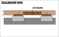
The rail joint of a bracket connection basically forms an unevenness in the track, as the rail ends must have a distance from one another to compensate for thermal expansion and cannot be screwed tightly - the screwing must be done with spring washers to enable the thermally induced movement of the rails to one another. When these areas are rolled over, jolts are therefore introduced into the track, where locally narrowly limited track subsidence can occur, which further intensifies the uncomfortable rollover noise that is typical of the lug joint. To improve the support of the weak point formed by the joint, the position of the joint gap was relocated from the sleeper compartment ( "floating joint" ) to a double or dome sleeper with continuous rib plates. This created the so-called fixed impact . Fixed joints on domed sleepers were common in many countries in the early twentieth century. They were also used in turnouts, for example in the Reichsbahn turnouts developed around 1930 . The effect of the support provided by domed sleepers is impaired by the fact that they make it more difficult to tamp. At the transition to welded connections, the continuous ribbed plates on dome sleepers had to be broken up again into two individual ribbed plates. Such welds are nevertheless complicated, and with the introduction of the gapless track, tie-bars were again dispensed with. Because the switch construction had to be changed for this, it took the longest to dispense with the dome sleepers in switches.

fixed joint with continuous support plate

fixed joint with separate production plates
floating shock

lashed, firm joint on the Arlbergbahn


In order to avoid stress at the joint, tests were made with other construction methods. Thus, in the bias joint , the ends bevelled, so that the wheels do not fall into the collision space. However, it has not proven itself, as the ends provided had to bear the maximum load despite being less thick and therefore tended to break. The same problem occurred with the blade joint (also known as Haarmann's rail joint ), in which the rail ends were cut in half lengthways and then screwed together. Here, too, the bar was prone to breakage (even in tests with a reinforced bar) so that the additional effort did not outweigh the benefits. A further attempt was made of approach straps, which are raised on the outside to the level of the upper edge of the rail. The wheels should be carried by the outer plate in the joint area. The effect, however, is very dependent on the state of wear, especially of the wheel running surfaces. At the beginning of the twentieth century, grommets were nevertheless widespread and the standard design for some railway administrations.
Krop bottles are used to connect rails in different states of wear . The offset results in a flat running surface despite the different heights of the two rail heads.
Emergency straps
Emergency strap assemblies are used to temporarily make broken rails passable again. The emergency tabs are pressed into the tab chamber with rail foot clamps because additional rail holes are to be avoided. In construction stages, the rails are also connected at the points that will be welded later. For broken thermite welds, cranked belly flaps are used because of the weld seam .
Welded joints


To shorten the installation time, to increase passenger comfort and to reduce noise emissions, one turns today's most widely the thermite as joining methods at. The reduction in noise emissions is 6 dB (A). The load-bearing capacity and durability of the rails is higher than with lashing. The forces that occur due to the linear expansion of the steel are absorbed by the bedding and transferred to the subsoil. The rails are compressed lengthways so that their cross-section increases slightly when heated. Accordingly, the requirements for the bedding are higher; the rails themselves can only expand in height and width.
Due to the increased demands on strength, durability and lower maintenance costs, thermite welding is now often replaced by the flash butt welding process . This is less time-consuming (a few minutes compared to around 40 minutes), can be automated and, even under high loads, has a durability that is two times higher than that of thermite welding. The decisive disadvantage of flash butt welding is the length consumption. One of the two rails must be loosened over its entire length for welding and then tightened again afterwards. Due to the length consumption, flash butt welding in switches and crossings as well as for final welding cannot be used. If the track is to be continuously passable in the meantime, fitting pieces must be installed at the end to compensate for this length consumption.
In order to achieve a harder head at the welding point of a splint with a hardened head by thermite welding, there is the SkV process with four portions of thermite mixture. Another further development of this aluminothermics led to the High Performance Weld (HPW) from Thermit Australia , in which, as usual, the liquid steel rises into the joint from below, but finally a "plug" is removed from the mold and into the top part of the Joint falls and the steel is suitably alloyed here in order to achieve an adapted higher hardness only here.
Electrical insulation
.jpg)
When using low-frequency track circuits , insulating joints are used to electrically separate track sections from one another. The glued insulating joints that have been customary since the 1960s behave like a standard rail profile from a thermal point of view, they do not allow reciprocal longitudinal movements and can therefore be used in seamless tracks. Nevertheless, they are a weak point.
Web links
- Youtube: Thermit welding
Individual evidence
- ↑ http://www.stiftung-naturschutz.de/fileadmin/img/pdf/Kleine_Anfragen/ka16-14932.pdf
- ↑ Thermitaustralia: High Performance Weld (HPW) by Thermit Australia youtube.com, video 05:15 min, July 3, 2012, accessed February 6, 2017.