
Screw lock
The screw lock or screw lock is a lock construction in guns. It was developed from around 1840, is one of the most frequently used breech designs and is mainly used today for large-caliber guns.

Basic requirements
The breech of the gun closes the barrel at the rear and must transfer the forces of the recoil through the barrel into the carriage structure when the shot is fired. To do this, it has to lock reliably with the pipe. Together with the cartridge, it must seal the tube gas-tight in order to use the propellant charge as completely as possible. The breech should provide protection against accidental firing. In principle, it must be possible to open and close the lock quickly with just a few hand movements when manually operated. Low weight and small dimensions are also required in order to minimize the dead tube length, that is, the length of the tube behind the cartridge or powder chamber. This dead pipe length together with the return path of the pipe determines the maximum pipe elevation for a given carriage construction.
Construction principle
Screw closures have in common that the gun core and a movable closure part have corresponding external and internal threads. The barrel is closed by screwing it shut before the shot is fired. In the beginning, the constructions were only slightly demanding screws that were screwed into simple threads. These were only gradually developed into locking mechanisms. At the beginning of the development, the nut thread could be in the core or on the screw, but later the combination with nut thread in the gun core and external thread on the screw prevailed and characterizes almost all designs from the second half of the 19th century. In the further development, the systems were divided into those with interrupted threads and those with uninterrupted threads.
Systems with interrupted threads
"Reffye" / "De Lahitolle" system
In France, at the beginning of the 1870s, the first fasteners with interrupted screws were designed. Two opposite segments of the locking screw were screw-threaded, the other two were smooth. The female thread of the pipe was constructed in the same way. The locking screw was axially displaceable in a swivel arm. The screw was turned 90 ° to open or close. The opened screw could then be moved axially back and forth. The screw was swiveled for loading or closing. 50% of the thread circumference was used for locking. If the closure was adequately dimensioned, high gas pressures could also be managed. At the same time, the sequence of movements was reduced to three movements - turning, shifting and panning - which drastically shortened the time for reloading. All previous systems were not yet fully connected to the pipe and had to be "assembled" each time. The propellant charge and the projectile were still separate in this system. The bullets did not yet have a ring for guidance in the trains, but rather guide knobs on the surface, which enabled the use of polygonal trains. Since the propellant charge was loaded via cartridges, there was no ejector for cases. It was ignited through an ignition hole. The system did not initially have a lock.
Two designers deserve special mention: de Reffye and de Lahitolle. Both used a basically identical breech, but the field cannons presented by de Reffye in 1873 were initially made of bronze and later also of steel. In 1875, De Lahitolle introduced the Canon Lahitolle de 95 mm , the first steel cannon barrel with a steel lock. The 95 mm cannon from De Lahitolle was initially intended for the Casemate de Bourges , among other things , but was only used very rarely after the Canon de 75 mle appeared in 1897 .
In France, many old bronze muzzle-loaders were also converted to this breech. For this purpose, the rear of the barrel was opened and a new gun core was attached to accommodate the locking mechanism. The 120 mm field cannon model 1858 was often equipped with a breech-loading breechblock. This model was named culasse 12 defense de fosse mle 1884 . These conversions were used in trench digs for the various French fortresses of the time.
The loading sequence:
- Insertion of the projectile and the propellant charge into the barrel.
- Swiveling the screw forward.
- Inserting the screw.
- Turn the screw 90 ° to the right for gas-tight sealing. If present, the lock engages.
- Introducing an ignition charge into the ignition hole. Ignition by ignition iron.
- Turn the screw 90 ° to the left to open. If available, the release lever must be operated beforehand.
- Pull out the screw.
- Swiveling the screw away. The weapon can be reloaded.
The threaded parts of the nut and screw do not contribute to the sealing, but they take care of the pressing of sealing cones in front of and behind the thread.

Sketch of the pipe after De Reffeye
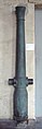
Barrel of a 75mm bronze gun made by De Reffye

Detail: lock with swivel mechanism and crank

Sketch of the pipe according to De Lahitolle
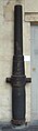
Barrel of a 95 mm steel cannon from De Lahitolle

Detail: lock with swivel mechanism and crank

In the background a culasse 12 Defense de fosse mle 1884 with the shutter open

Canon 12 de culasse modèle 1884 , a bullet with guide knobs on the left edge


Baranowski system
Baranowski, a Russian designer for the Nobel company in Saint Petersburg, designed guns with locking mechanisms at around the same time as De Reffye and De Lahitolle. The closure was a screw closure with an interrupted thread based on the French model. Baranowski's innovation, however, was the use of a trigger mechanism for ignition and the design for cartridge ammunition. Baranowski avoided problems with gas tightness through the lid-like effect of the cartridge bottoms. The lock was also fitted with a lock for the first time from the start. The trigger could not be pulled until the shutter was fully closed. The cock was automatically cocked when it closed. Cartridge ammunition requires an ejector for efficient use. Baranowski constructed one. It was activated automatically when the shutter was opened. The gun barrel and the soul were split in two and were shrunk on. Baranowski used steel as the material.
- The loading sequence
- Slide the cartridge into the tube.
- Swiveling the screw forward.
- Inserting the screw.
- Turn the screw 90 ° to the right for gas-tight sealing. The lock engages.
- Firing by triggering the tap.
- Unlock and turn the screw 90 ° to the left to open.
- Pull out the screw.
- Ejecting the sleeve.
- Swiveling the screw away. The weapon can be reloaded.

Baranowski closure in the open state

"De Bange" system

Charles Valérand Ragon de Bange also presented a locking mechanism with an interrupted thread in 1877. He solved the previously existing problem of gas tightness by introducing a plastic seal in the form of an asbestos-grease ring. Due to the gas tightness, the closure is particularly suitable for cartridge ammunition and consequently also for large to very large calibers. De Bange took over the sliding / pivoting mounting of the previous French constructions, but improved details considerably. The De-Bange lock had a lock, a secure trigger mechanism and additional handles that made it much easier to swing out. Unlike the previous systems, the thread is divided into three segments. An ejector for sleeves is not provided. The essential elements of the clasp are still used today.
The 80 mm, 90 mm and 155 mm mle 1877 cannons designed by Ragon de Bange were introduced into the French army in 1877 and 1879, respectively. Variants as field cannons and for turrets were developed. The former did not yet have a return pipe, as they were not ready for series production until the end of the 19th century. The Royal Navy and the British Army also use the locking system designed by de Bange for the new introduction of breech loading. Other states, such as the USA, also imported weapons according to this system. The de Banges construction was in competition with the wedge locks developed by Krupp and the Baranovskian constructions. For example, while Serbia preferred the French construction in 1884, Romania preferred the Krupp construction in 1885. In 1884, Russia turned away from the wedge lock in the M1877 9/35 inch cannon and introduced the screw lock, which was to become the dominant lock design for large-caliber Russian and Soviet artillery weapons.
The loading sequence:
- Insertion of the projectile and the propellant charge into the barrel.
- Swiveling the screw forward.
- Inserting the screw.
- Turn the screw by 60 ° to the right for gas-tight closure. The lock engages.
- Firing by triggering the tap.
- Unlock and turn the screw 60 ° to the left to open.
- Pull out the screw.
- Swiveling the screw away. The weapon can be reloaded.

Functional sketch of the De-Bange lock

De-bange closure, closed

De-bange closure, half open
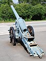
De Bange gun 155mm mle 1877 with the breech removed, the nut thread in the gun body can be clearly seen


Conical screw cap
In Great Britain the screw cap was used for all calibers up to 6 inches together with brass cartridges. In contrast to other countries, in which wedge locks from the Krupp or Nordenfelt system were generally used for rapid-fire cannons , Great Britain also held on to the screw lock for rapid-fire cannons of the QF series (Quick Fire). Grenade cartridges were also used here. When developing the QF 6 inch, however, there was a very strong recoil, which required a stronger lock. This in turn made a larger number of thread webs necessary. However, such a closure would become very long. Three movements were required to open the breech: turning the breech, pulling it out and pivoting it to the side. Together with the length, there was an unfavorable mechanical design for the locking mechanism, which could hardly be implemented in practice. Elswick solved the problem in 1890 by making the closure body conical. At its front end it was smaller in diameter than at its rear end. This enabled the number of movements to be reduced to two: turning the screw and pulling it out with simultaneous swiveling. By staggering the segments on the conical and cylindrical part, the forces in the pipe were diverted more evenly.

Bolt of a British 6-inch gun

Ogival screw lock
Arent Silfversparre , who worked for the Swedish arms factory Bofors , solved the problem in a similar way in the early 1890s. Instead of a conical locking screw, however, he used an ogival screw. Bofors used this design well into the 20th century. Both the ogival and the conical screw lock had the disadvantage that the thread bars at the tip with a smaller diameter could not absorb as high locking forces as those at the rear end. The possible force absorption was therefore not proportional to the length of the lock. In addition, the shapes of the closure and base were relatively difficult to manufacture.

Sketch of the Bofors system

Ogival lock system Bofors

Movement of the Bofors lock


Welin screw lock system
The screw cap had proven its practical suitability by the beginning of the 1890s. However, it was disadvantageous that only 50% of the circumference was used for locking. Stronger recoil forces could only be absorbed by longer locks, even if Elswick and Bofors had suggested solutions here, this disadvantage basically remained. Around 1889/90, the Swedish designer and industrialist Axel Welin developed a new locking system, which is named after him. He introduced two more thread segments, but they were smaller in diameter than the original two. As a result, 2/3 of the circumference were now available for locking. More segments were added later, further increasing the scope involved in locking. This made it possible to go back to the cylindrical screw plug, which is easier to manufacture. In this construction, the tube on the bottom piece was extended on one side, which made it easier to swing out the lock and made a more compact lock mechanism possible. This design feature can be seen in the picture of the Russian 305 mm cannon. This breech can be opened (turning - swinging) or closed (swinging - rotating) with two movements and thus enables the construction of large-caliber, rapid-fire guns.

Welin screw lock system

Welin system from a Russian 305 mm cannon


Comb closure
In the case of the comb lock, the screw thread is replaced by combs running parallel without a pitch, so the lock block only needs to be turned when closing after insertion, but not moved forward. This eliminates the force otherwise required to tighten the screw. This tightening is actually unnecessary with self-lid cartridges. In addition, loosening or loosening of the screw due to vibrations is prevented, which can occur especially with screws with a steep incline. Erhardt designed such a closure as early as 1902, but it was not able to establish itself in the long term. Screw fasteners with a low pitch are still in use.
Krupp introduced another type of comb lock. As with the Welin system, several segments of different diameters were used, and the locking screw itself was also conical, as in the Elswick design. This construction could not prevail either.
Systems with uninterrupted threads
Tail screws
The tail screw lock was a very early and simple attempt to convert muzzle-loaders into breech-loaders. The tube was simply opened in the rear area and provided with a nut thread. A kind of screw was used as a closure, which is screwed in after loading. As with the muzzle loader, it was ignited via an ignition hole. There was no ejector for sleeves.
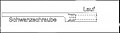
Functional scheme of the tail screw
Lock construction according to Armstrong
One of the first breech-loading locking mechanisms was the Armstrong lock. It is not a thread closure in the strict sense, because a metal block is inserted into the pipe from above. Only the lock is made by a force-fit screw that is screwed into the tube from behind and presses the metal block against the rear edge of the powder chamber. This construction connects elements of the wedge lock and the screw lock. A copper ring attached to the block seals the powder chamber gas-tight. The individual elements of the lock are not coupled to one another, so opening and closing the lock are complicated and time-consuming. Since Armstrong used conventional propellant bags instead of grenade cartridges or cartridges, gas tightness could only be ensured with a great deal of additional effort.
The Armstrong lock was used by the Royal Navy and the British Army in the RBL series (Rifled Breech Loader) from the 1850s onwards . Since the manufacture and maintenance of the guns and the ammunition were complex and therefore expensive, and on the other hand there were no significant advantages compared to muzzle-loaders, the Royal Navy had the production of such guns ceased from 1864 and went back to the muzzle-loader, this time with a rifled barrel (RML- Rifled Muzzle Loader). On the British side, guns with the bolt designed by Armstrong were used in the Second Opium War . The Japanese army successfully used cannons with this locking system in the Boshin War .
Armstrong and Whitworth developed their closure further. The block or wedge was omitted, the closure and locking were ensured by the screw connection alone. Both screwed and screwed locking screws into the pipe were used. In principle, these constructions were useful. However, the thread used was not interrupted. To close or open the screw, the screw had to be turned several turns, which was relatively time-consuming.

Armstrong and Whitworth shutter designs

Eccentric screw lock system Nordenfelt / "Arsenal de Bourges / Atteliers Puteaux" system
The Nordenfelt closure was developed in France in the 1890s by the company owned by the Swedish designer Thorsten Nordenfelt. The bottom piece here was cylindrical with an uninterrupted thread and a recess on one side. The axis of rotation of the cylinder was in the direction of the pipe's longitudinal axis, but shifted downwards by about 100 mm. With the axis of rotation shifted downwards, the recess exposed the rear end of the tube in the loading position. In this position the gun was loaded. The gun was made ready to fire by turning the bolt clockwise by 120 ° around the longitudinal axis of the barrel.
The lock had an unscrewing protection, a lock, a manual ejection mechanism and a re-cocking trigger (pictures 1, 2, 3, 4).
By removing the anti-twist lock, the lock could be removed by simply unscrewing it. The closure had clear advantages over the De Bange closures that had been used very frequently in France up to that point. It no longer had to be cranked, pulled and swiveled, just the 120 ° turn. The sleeve was ejected from the tube through an ejector located behind the closure. The easy-to-remove breech made the gun easy to maintain and clean. Due to the very simple construction, the closure was less prone to malfunctions and dirt.
The lock came on the various versions of the Canon de 75 mm modèle in 1897 , on the 1 × 75 mm / 2 × 75 mm Galopin rotating submerged towers and until the 1930s on 75 mm fortress guns of the Maginot Line Commitment.
The loading sequence:
- Slide the cartridge into the barrel. The trigger is locked (Fig. 1).
- Press the release button and turn the block to the right to the end stop.
- The lock engages automatically in the end position, the trigger is released. The weapon is ready to fire. (Picture 2)
- The spring-loaded trigger is cocked by pulling the trigger. There is a recess at the end of the rack, the stopcock snaps back to its starting position. This strikes the ignition pin on the primer and ignition takes place.
- After the shot has been fired, the release button is pressed again and the slide is turned to the left as far as it will go. The trigger is automatically blocked.
- The spring-loaded ejector fork is released by the locking screw and automatically ejects the sleeve.
- The weapon is ready for loading again. The trigger is locked.
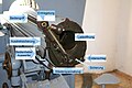
Image 1: Open closure with labels

Image 2: Closed lock with labels

Fig. 3: Tube without closure with designations

Fig. 4: Sketch of the locking mechanism
Canon de 75 loading and firing


See also
- Canon de 7 modèle 1867 Canon de 7 rayé se chargeant par la culasse M / 1867, a French breech-loading gun
Web links
literature
- Lueger, Otto: Lexicon of the entire technology and its auxiliary sciences , Vol. 8 Stuttgart, Leipzig 1910., pp. 781–784.
- Brockhaus' Konversationslexikon, FA Brockhaus in Leipzig, Berlin and Vienna, 14th edition, 1894–1896
- Meyers Großes Konversations-Lexikon , Volume 7. Leipzig 1907, pp. 692–709.
Individual evidence
- ↑ Rheinmetall Waffentechnisches Taschenbuch 5th edition 1980, p. 306