
Wedge lock

The wedge lock is a lock construction that has been used over the years in a wide variety of weapon technology designs.
Basic requirements
The bolt of the gun closes the barrel to the rear and transfers the force of the recoil via the barrel to the mount when the shot is fired. In guns that fire caseless ammunition, it prevents propellant gases from escaping. When firing cartridge ammunition, a mechanism operated by the semi-automatic guns automatically ejects the case when it is opened. In principle, it must be possible to open and close the lock quickly with just a few hand movements when manually operated. For guns that fire cartridge ammunition, the lock attached to the locking wedge, resp. the firing device must be secured against unintentional firing. A low weight and small dimensions are also required in order to minimize the dead tube length, that is to say the length of the tube behind the cartridge or powder chamber. This dead pipe length together with the return path of the pipe determines the maximum possible increase for a given carriage construction.
history

Muzzle loaders remained the dominant form of construction for artillery pieces until the middle of the 19th century. Since the battles at that time were conducted both on land and at sea from a few hundred meters away, the shooting performance was sufficient for the requirements of the time. With the advent of rifled infantry weapons, using long bullets, the ranges of the muzzle-loaders were no longer sufficient to effectively combat the infantry units, as they could now operate outside the range of the muzzle-loading guns. For this reason, the Italian Giovanni Cavalli tried in 1846 to transfer the system of rifled infantry weapons to the artillery and so he constructed a rifled 30-pounder breech-loader. The closure he chose this as opposed to Wahrendorff which the guns for his piston closure was using a wedge lock. However, this closure did not prove itself as it was designed too weakly. In the following years the rifled guns were equipped with the Wahrendorff piston or, in England, with the Armstrong breech.
In Prussia, the idea of the wedge lock was taken up again in the development of the towed breech loader and introduced in 1862 as Kreiner's wedge lock in fortress and siege artillery. The successor to this construction was the so-called Wesener wedge lock in the field artillery in 1864. However, since this was designed too weakly on the whole, production was stopped again in 1866 and it was replaced by a modified Kreiner wedge lock in 1867.
Parallel to the Prussian developments, the Krupp company developed its own locking systems. On October 29, 1862, the Krupp company received a patent for a flat wedge lock in England. In 1864 the so-called "simple round wedge lock" followed for the field artillery. In 1866 this was redesigned for use in the large calibers and provided with a transport screw for easier movement when opening and closing. The cumbersome type of locking, for which a locking bolt attached to the front was used, was eliminated with the improved construction from 1868. This closure remained in use until the introduction of the rapid fire closures in the 1890s.
With the introduction of the low-smoke propellant charges in the 1880s, the thick clouds of smoke when firing disappeared and there was no longer any need to wait until the next shot was clear, so there was the possibility of being able to shoot faster. To solve this question, two main problems had to be solved, firstly the acceleration of the loading process and secondly the question of the stability of the guns when firing.
The development of rapid fire closures was favored by the progress that had been made in the meantime in the manufacture of metallic cartridges. Initially, the Krupp rapid fire round wedge lock C / 87 was used. As early as 1888, Krupp was able to equip a 13 cm and in 1890 a 15 cm cannon with a rapid fire breech. The rapid-fire round wedge lock C / 87 was replaced in 1895 by the Leitwell lock, which was then the predominant type of lock for years. In the further course of the technical development it came to the construction of further locking systems.
Construction principle
With a wedge lock, a wedge slides either horizontally or vertically into the pipe and closes it off at the rear. The wedge shape and the movement of the wedge ensure both gas tightness and locking. More recent designs of the wedge lock are the Armstrong lock, Krupp's Leitwell lock and Erhardt crank lock, which differ in the design of the operating and locking elements. Gas tightness and reliable locking are advantageous. With the exception of the development by Armstrong, the design is also characterized by simple operation and short loading times as well as the possibility of automation. The relatively high weight and the relatively large dead pipe length are disadvantageous. Further developments are the drop block lock and the reversible wedge lock, which are characterized by low moving masses and use gravity to move the wedge and thus allow even faster reloading. Due to their low mass, however, they can only be used for guns up to a caliber of approximately 75 mm.
Description of the individual systems
Lock construction according to Armstrong

In the Armstrong closure, a metal block is inserted into the tube from above. The locking is established by a force-fit screw that is screwed into the tube from behind and presses the metal block against the rear edge of the powder chamber. A copper ring attached to the block seals the powder chamber in a gas-tight manner. The individual elements of the closure are not coupled to one another, so opening and closing the closure are complicated and time-consuming. The further development of the original Armstrong fastener led to the designs by Joseph Whitworth and Armstrong, which can be assigned to screw fasteners with uninterrupted threads .
Prussian double wedge lock
There were two different versions depending on the intended use:
- Double wedge lock for field artillery,
- Double wedge lock for siege and fortress artillery.
The two systems only differed in certain design features, which were due to the different dimensions of the gun barrels. The following explanations apply to the second version.
In the original version from 1862, the closure consisted of two massive wedges inserted across the base of the tube, which, when their inclined planes lay on top of one another, formed a prism. By moving the two wedges against each other, the height of the prism could be changed so that the wedge could easily be pulled out of the wedge hole. This shift was made possible or supported by the spindle, which was screwed into the face of the front wedge. The spindle was held in a pierced, hook-shaped extension of the rear wedge. The movements of the lock were controlled by two grooves on the rear of the rear wedge, in which the limit screw engaged. Safety elements against unintentional opening of the lock were not available. To obturator pressboard discs were provided. In an extreme emergency, it was possible to shoot without the targets. On the whole, the closure was usable, but there were always malfunctions, as the movable wedge formed the bottom of the soul in this construction and the powder slime that was deposited here when the shot was fired impeded the function of the closure.
Over the years this construction has been changed several times. As early as 1864, the lock was rotated, similar to the design of the so-called Wesener's wedge lock for the field artillery, so that the fixed wedge was now on the cargo side. In addition, a steel plate has now been embedded in the front wedge so that the complete closure no longer has to be replaced in the unavoidable burns caused by the powder gases. The steel plate was square and clearly protruded above and below the front wedge. These sides of the steel plate were rounded and thus engaged in corresponding grooves in the wedge hole. In addition, the steel plate was provided with a circular recess, in which the so-called "copper eyelid" could be inserted. As a further change, the limit screw previously attached to the side has been replaced by one attached to the front. As a safeguard against unintentional opening of the lock, an angle piece was attached to the left side of the tube, under which the crank washer came to rest when the lock was closed. The diameter of the washer was reduced on part of the circumference so that after a certain turn of the crank the washer was exposed and the lock could be pulled out.
In another variant, around 1866, the limit screw attached to the front was replaced by a spring-loaded toggle, which made it possible to dismantle the lock without using a tool. In addition, Kreiner's copper liner was replaced by the so-called Broadwell ring.

Prussian double wedge lock in the design from 1862
Prussian double wedge lock in the design from 1864

Prussian double wedge lock in the design from 1866
Krupp round wedge
With the development of ring tubes and the associated increase in powder loads, Krupp quickly discovered that the flat wedge locks that had been used up until then for heavy tubes (caliber greater than 72 pounds) were not sufficient. Based on the experiences that Krupp had made with round wedges for the lighter calibers (here the round wedge locks for field guns developed especially for the Russian army), the development of the round wedge locks for the heavy tubes came about. Two developments in particular have taken place here:
- Round wedge lock C / 1866
- Round wedge lock C / 1868.
Round wedge lock C / 1866
The round wedge lock C / 1866 essentially consisted of the following individual parts (data and description essentially relate to the 8-inch rifled (Krupp'sche) reloading cannon in the service of the Imperial and Royal Navy):

- Locking wedge
- Locking plate
- Transport screw with the half nut. The transport screw was about 3/4 "thick with a double right-hand thread at a pitch of about 1".
- Tightening screw. The tightening screw was approximately 2½ "thick with a simple right-hand thread on a pitch of approximately 1/4".
- Tightening nut
- crank
- Locking pin with locking pin and toggle. The screw in the toggle was approximately 1.33 "thick with a three-start left-hand thread and a pitch of approximately 1¼".
- Lock chain or pawl
- Lulling
Functionality:
- 1. Close the clasp.
The locking wedge was pushed into the wedge hole with the transport screw by means of the outer collar 2.3, which was in contact with the bearing 2.4, which was firmly connected to the locking wedge, until the inner collar 2.2 of the transport screw was attached to the half nut, which was firmly attached to the tubular body (The wedge could not be firmly inserted into the wedge hole with the transport screw. This was only possible with the tightening screw.) At the same time, the tightening nut was pushed into the wedge hole by means of the collar 1.1, which was in contact with the locking plate that the tightening nut could be fixed with the locking bolt. After this was done, the crank was moved from the transport screw to the square of the tightening screw. When the tightening screw was turned from left to top to right, i.e. clockwise, the collar 1.1 came loose from the locking plate, and the tip 1.2 of the tightening screw, which was guided in a hole in the wedge body, pressed against the bottom of the hole and pushed the tightening nut against surface 5.1 of the locking bolt. This process blocked the tightening nut and could not go back any further. As the tightening screw was turned further, it pushed further out of the tightening nut in direction “B” and pushed the locking wedge further into the wedge hole. The process was ended as soon as the storage 2.4 of the transport screw hit the inner collar 2.2 of the transport screw, which was already fixed by the half nut, and no further movement of the locking wedge was permitted.
- 2. Open the lock.
By turning the tightening screw from right over top to left, i.e. counterclockwise, the tightening screw was moved outwards in direction "A" and was firmly attached to the closure plate with collar 1.1. When this was done, the tightening nut was pressed against the locking bolt when the tightening screw was turned further and lay firmly against the surface 5.2 and was thus prevented from moving further. As the tightening screw was turned further, the locking wedge was pushed out of the wedge hole and the tension was released. In the relaxed state, the locking bolt could then be pulled out of its mounting, a rotation of approx. 270 degrees was sufficient and the locking wedge was thus free. After the crank was now put back on the transport screw, the inner collar 2.2 of the transport screw was released from the half nut by turning the same from right over top to left and lay on the bearing 2.4. During the following turns of the transport screw, the locking wedge was pushed completely out of the wedge hole. This movement was originally controlled with a so-called border chain. In later designs, this was replaced by a pawl, which was guided in a groove on the lower side of the wedge.
Round wedge lock C / 1868
Already after a relatively short time it was found that the round wedge lock C / 1866 did not meet the requirements in the long term, for two main reasons: on the one hand, the cumbersome type of locking, which was caused by a locking bolt attached to the front, and on the other hand, the inadequate Lideration by the cup-shaped copper washers, which had to be turned over with each shot. The problem arose after a slow-burning powder, the so-called prismatic powder, had meanwhile been introduced in Russia for the large calibers, which, with the previous ignition and the slower burning rate, placed a high degree of one-sided strain on the lids, which ultimately contributed to not exactly fitting eyelid bowls could lead to powder penetrations. For these reasons, the round wedge lock C / 1866 was redesigned and adapted to the new requirements. There were essentially three features that were changed_
- Simplification of the locking by eliminating the front locking bolt,
- Replacement of the ignition by a central ignition by the locking wedge,
- Replacement of the cup-shaped copper shells by the so-called "Broadwellring".
The round wedge lock essentially consisted of the following individual parts (the following description essentially refers to a lock as it was used on the 9-inch Russian coastal cannons :):
- Locking wedge
- Locking plate
- Transport screw
- Tightening screw
- Locking socket with handle. The locking sleeve was a cylindrical hollow body, which was provided with a thread on the inside and several rings on the outside. Except for the first outer ring (3), these were removed to about 1/3 of the circumference. A small nose (6) was also attached to this ring, in which a small handle was inserted. In the rear surface of the wedge hole there were grooves in which the ribs could be supported when the lock was closed.
- Pawl
- crank
- Lulling. In response to the experiences made with Russian field guns in 1864, the so-called Broadwellring was used.
Various fastening elements were also available.
In the following, only the function of the tightening screw in connection with the locking bush is described. The mode of operation of the transport screw has already been explained above for version C / 1866.

- 1. Close the clasp.
After the lock had been pushed into the wedge hole using the transport screw - the process was finished as soon as the ring (3) touched the surface (1) - the crank was moved from the transport screw to the square of the tightening screw. When the tightening screw was now turned from left to top to the right, i.e. clockwise, the locking bushing followed the rotation due to the friction present in the thread between the tightening screw and the locking bushing, and the ribs of the same pushed into the corresponding grooves in the pipe body. The movement was limited by the small nose (6), which had been released from its upper position with the rotary movement and now found its stop in the lower position. A corresponding cutout was made in the closure plate to support the tightening screw. If, for whatever reason, the locking sleeve did not follow the rotary movement, this could be carried out using the small handle. As soon as the little nose was in the lower position, the locking sleeve was fixed. By turning the tightening screw further, the locking wedge was pushed further into the wedge hole through the cylindrical shoulder (2) of the tightening screw. The lock was closed as soon as the lock plate rested on the first ring and no further movement was possible.
- 2. Open the lock.
By turning the tightening screw from right over top to left, i.e. counterclockwise, the collar (4) of the tightening screw first pressed against the locking plate and thereby pushed the locking wedge outwards and thus loosened it. As soon as the locking wedge was exposed, the tension between the ribs of the locking bushing and the grooves in the tubular body was released, and the locking bushing could again follow the rotation of the tightening screw. As soon as the little nose had reached the upper position again, the ribs had completely protruded from the grooves and the locking wedge was exposed. The locking wedge was then completely pulled out with the transport screw. The process was limited by the pawl, which was guided in a groove on the underside of the wedge.
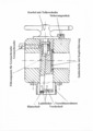
Krupp's Leitwell closure

With Krupp's Leitwellschluessel the wedge (A) is pushed transversely to the longitudinal axis into the gun barrel. The wedge can either be designed as a flat wedge (flat wedge lock) or as a cylinder (round wedge lock), but always has a prismatic or conical shape to enable play-free guidance. The wedge is guided by the guide shaft (B). The guide shaft engages in a nut (T). The nut and guide shaft have a thread with a large pitch. By turning the handle (B1) the wedge is pushed into the pipe or pulled out again. Due to the pitch of the thread, three quarters of a turn is sufficient. The handle is blocked by the driving safety device (O) and prevents the lock from opening unintentionally. The lock is locked by a bolt collar at the end of the guide shaft, which engages in a cutout in the pipe. When the lock is opened, the bolt collar is first pulled out of the cutout by turning the guide shaft and releases the wedge again. It is fired with the help of the trigger (K) on the slide. This breech enables rapid reloading and paved the way for the development of rapid-fire cannons.
Slider crank lock according to Erhardt
With a slider crank lock, the slider crank (Sk) rotates around the crank bolt (kb) that is attached to the pipe. There is a sliding piece (g) on the shorter lever arm of the slider crank, which runs in a groove (nt) of the wedge that leads obliquely to the front and outside. If the crank handle is pulled back on the handle (hg), the wedge is pulled out over the sliding piece and the groove. It is advantageous that the slider crank only needs to be turned by approx. 130 ° in this design. The closure is locked in the end position by the fact that the sliding piece at the end of the groove falls into a hole surface. To unlock, the sliding piece must therefore first be pulled up a short distance by pulling the handle. Usually an additional lock in the form of a pawl is also installed in the handle, which latches into a recess in the tube when the lock is closed. Just like the Krupp guide shaft lock, this construction enabled rapid reloading and thus the development of rapid-fire cannons. The Krupp design of the sliding crank lock differs in the shape of the slide and the locking of the closed lock.
Drop block lock

In the case of the drop block lock originally developed by Gruson , the wedge slides out downwards and thus releases the tube for reloading. To do this, first move the trigger (b) upwards a little. This causes the firing pin (h) to slide backwards a little and clear the way for the wedge. Similar to the sliding crank lock according to Erhardt, the wedge is moved by turning a sliding crank, the slide of which is guided in a groove in the wedge that leads to the front and top. In principle, this is a crank lock rotated by 90 ° to the longitudinal axis of the pipe. When the wedge is lowered, the firing pin spring (i) is tensioned via a tension pulley (e). The pins connected to the tension pulley are guided in the groove on the left-hand side of the wedge. Tensioning the spring pulls the firing pin backwards and the head of the trigger rod (a) lies in front of the firing pin. This prevents firing if the breech is not fully closed. When the wedge is moved down, the ejector bolt (m) is turned and the sleeve is first loosened by the ejector nut (o) and then pulled back out of the tube. This closure also enables quick reloading.
Reversible wedge lock
With the foldable drop wedge lock, the lock is first pulled downwards when opening and then turned backwards around a shaft that is perpendicular to the pipe. In principle, this is a further development of the drop block lock similar to the tilt block lock commonly used in handguns. It is used with small-caliber rapid-fire cannons. With the Nordenfelt system , only the rear part of the fastener is rotated. Variants of this design principle are the closure based on the Nordenfelt system, the Driggs-Schröder system , which was essentially only used by the US Navy , as well as the Maxim-Nordenfelt system and the Sarmiento system
Semi-automatic gun
Semi-automatic guns are usually recoil guns with a wedge lock that fire cartridge ammunition. After firing, the tube is accelerated and the recoil rearwardly through the recuperator brought back to normal position, while the shutter opens and ejects the sleeve. The shutter remains open. The next cartridge can be inserted, the slide closes and the weapon is loaded.
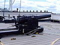
Armstrong breech, here British 7-inch cannon (110 lb)
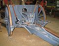
Slider crank lock according to Erhardt, here 7.7 cm field cannon model 1896

Drop block lock, here a British 25 pounder

Drop block lock, here QF 4 inch Mk XVI

Reversible wedge lock system Nordenfelt , here 57 / 48mm cannon


literature
- Lueger, Otto: Lexicon of the entire technology and its auxiliary sciences . Volume 8. Stuttgart / Leipzig 1910, pp. 781 to 784.
- Meyer's large conversation lexicon . Volume 7. Leipzig 1907, pp. 692 to 709.
Web links
Individual evidence
- ↑ Josepf Schmölzl: Supplementary weapon theory. A textbook for knowing and studying modern firearms . Literary-artistic establishment of the JG Cotta'schen Buchhandlung. 2nd Edition. Munich 1857, p. 225.
- ↑ Diedrich Baedecker: Alfred Krupp and the development of the cast steel factory in Essen . GD Baedecker, Essen 1889, p. 52.
- ↑ Krupp 1812 to 1912 . Verlag von Gustav Fischer, Jena 1912, p. 152.
- ↑ Krupp 1812 to 1912 . Verlag von Gustav Fischer, Jena 1912, p. 346.
- ↑ Krupp 1812 to 1912 . Verlag von Gustav Fischer, Jena 1912, p. 349.
- ^ Karl Theodor von Sauer: Outline of the weapon theory . Literary and artistic establishment of the IG Gotta'schen Buchhandlung, Munich 1869, p. 354.
- ↑ J. Schott: Plan of the weapon theory . Eduard Zernin, Darmstadt / Leipzig 1868. pp. 63 to 65.
- ^ W. Wilhelmi: The 8-inch rifled (Krupp'sche) reloading cannon in the service of the Imperial and Royal Navy . In: Johannis Ziegler: Archives for marine life . Volume 4. Self-published, Vienna 1868, p. 204.
- ^ W. Wilhelmi: The 8-inch rifled (Krupp'sche) reloading cannon in the service of the Imperial and Royal Navy. In: Johannis Ziegler: Archives for marine life. Volume 4. Self-published, Vienna 1868, p. 274.
- ^ Anton Zdenek: Notes on the Royal Russian Artillery . In the KK Artillery Committee: notifications about objects of artillery and war science . Publisher: W. Braukmüller, Vienna 1869, p. 400.