Shadow mapping
Shadow mapping is a computer graphics method used to represent shadows . The concept was presented in 1978 in the paper "casting curved shadows on curved surfaces" by Lance Williams. Shadow maps are used for both offline rendering and real-time applications.
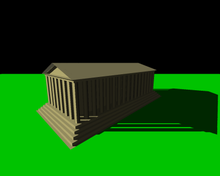
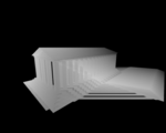
Shadow mapping generates shadows by testing whether a pixel is visible from a light source. First the so-called shadow map is generated. This is a depth map generated from the point of view of the light source. This contains information about the smallest distance between objects in a scene and the light source ( Z buffer ). By comparing the distance between the object to be rendered and the light source and the corresponding point in the shadow map, the shadow cast can be calculated.
Working principle
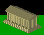
The rendering of a scene with shadows with the aid of a shadow map essentially takes place in two steps. First, the scene is rendered from the point of view of light and the depth information is saved for each visible object. The scene is then rendered normally, with the shadow map being used to determine for each pixel whether it is visible to the light. If this is not the case, the pixel is rendered shaded.
This technique offers less accurate results than shadow volumes , but is generally faster to compute. In addition, shadow maps can be implemented without the aid of the stencil buffer and allow the drawing of soft edges.
algorithm
Draw the shadow map
First, the depth map is created for each light. A perspective projection should be used for point light sources , while an orthogonal projection is suitable for directed light sources with parallel rays (such as the sun) . To do this, the scene is rendered from the position of the light and the depth information is saved. The depth map is often saved as a texture in the graphics card's memory. In order for this rendering process to run as efficiently as possible, both the light and the color calculation can be omitted or switched off.
Every time the position of a light or an object changes in the scene, the depth maps must be recalculated.
Shade the scene
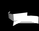
As a second step, the scene is rendered from the view of the camera and the shadow map is applied to the individual pixels. This step essentially consists of three operations. The first is to transform the relative coordinates of an object compared to the camera to the corresponding relative coordinates as seen from the light. Second, the coordinates are compared to the depth map, and last, the object is drawn as illuminated or shaded.
Uniform shadow mapping
When drawing the actual scene, the distance to the light source for each pixel can be compared with the distance that stands for this point in the depth texture. If the distance of the pixel is greater than the distance stored in the texture, the pixel is in the shadow.
In the case of global light sources such as the sun, the area over which the depth texture extends is very large. The spatial resolution of the shadow is therefore very low. The uniform distribution of the texture space over the affected area also means that the shadow resolution perceived by the viewer is very low in the vicinity, while an unnecessarily high resolution is achieved in the distance.
Perspective Shadow Mapping (PSM)
Perspective Shadow Mapping expands the projection matrix of the light by a perspective component of the observer projection . The previously square extension area of the shadow texture is thus deformed to a trapezoid , which has its narrow side towards the viewer and thus offers much more texels per unit of measurement there than in the distance. The method works well for scenarios where the viewer's line of sight is largely perpendicular to the direction of light. However, the method has some numerical dead spots in which the projection matrix takes on invalid values or inverts the shadow.
Light Space Perspective Shadow Mapping (LiSPM)
Light Space Perspective Shadow Mapping (used in SpellForce 2 , for example ) is an extension of the PSM method, which uses modified formulas to freely select the degree of perspective distortion of the light projection. This method corresponds to the PSM method if the viewing angle is perpendicular to the direction of light. The more parallel the viewing direction and the light direction, the smaller the perspective distortion, until the method reverts to normal uniform shadow mapping in the case of parallelism. This method prevents the dead spots of PSM. The optical result is still strongly dependent on the direction of view.
Cascaded Shadow Mapping (CSM)
Cascaded Shadow Mapping (used for example in 3DMark 2005 and 3DMark2006) prevents the uneven distribution of the shadow texel density by using several nested shadow maps for different distances. Each individual shadow map is projected uniformly or can be projected in perspective using one of the above variants. The method is easy to implement and provides flexibly adjustable shadow quality for all distances, but requires a multiple of the computing time and the graphics card memory of other methods.
Dual Paraboloid Shadow Mapping (DPSM)
The traditional technique of shadow mapping uses only a depth map. But if you want a light shining in several directions, e.g. B. to realize a point light , the traditional method is no longer sufficient. In the course of time, this led to dual paraboloid shadow mapping, a technique in which the space around the light source is projected onto two paraboloids , which correspond to two depth maps. This method is almost as efficient as traditional shadow mapping, but also has disadvantages, which are mainly related to the distortion caused by the projection onto the curved paraboloid . However, these can be reduced to a minimum by suitable countermeasures.
Dual paraboloid mapping was first described in 1998 in the publication "View-independent environment maps" by Wolfgang Heidrich and Hans-Peter Seidel.
Other methods
There are other ways to improve the display of shadow maps, but they are not suitable for calculation in real time. You work by segmenting the scene and assigning shadow texture fragments of different sizes to these segments according to various quality criteria. There are also real-time variants, but the division of the scene in real time is problematic and leads to visible jumps in the shadow quality in the image.
Web links
- Hardware Shadow Mapping (PDF, English) - Article explaining the implementation of shadow maps using the graphics card.
- Dual Paraboloid Shadow Mapping - Tutorial on the Dual Paraboloid Shadow Mapping technique.
Individual evidence
- ^ Lance Williams (Computer Graphics Lab, New York Institute of Technology, Old Westbury, New York): Casting curved shadows on curved surfaces. (PDF) In: ACM SIGGRAPH Computer Graphics: Volume 12, Issue August 3 , 1978, pp. 270-274 , accessed April 5, 2010 (956 KB, ISSN 0097-8930 ).
- ^ Rouslan Dimitrov: Cascaded Shadow Maps. (PDF) NVIDIA Corporation, August 2007, accessed April 5, 2010 (1.58 MB).
- ↑ Wolfgang Heidrich, Hans-Peter Seidel: View-independent environment maps . In: Proceeding HWWS '98 Proceedings of the ACM SIGGRAPH / EUROGRAPHICS workshop on Graphics hardware . Association for Computing Machinery, New York 1998, ISBN 1-58113-097-X , pp. 39 ff ., doi : 10.1145 / 285305.285310 .


