Spaldingbahn
The Spalding Railway was a field railway system developed in 1884 similar to the Decauville Railway, invented and patented 8 years earlier in France .
history
In 1884, the entrepreneur Heinrich Andreas Spalding (born August 18, 1844) from Jahnkow near Glewitz was the first German industrialist to use a narrow-gauge "hiking railway" at his own risk for the transport of forest products in the Royal Prussian Forest District Grimnitz in the Mark Brandenburg . The success that Spalding achieved there in two large pine trees in the area at a distance of 2 and 3 km from the navigable body of water, the large Werbellin Lake , resulted in the transported amount of 8,536 solid meters of pine timber and firewood over an average distance of 4 , 7 km a transport cost reduction of 11,387 marks. The procurement costs for the forest railway line amounted to 47,000 marks, so that the railway system should have paid for itself in four years.
At the inauguration of the Spalding Railway, Kaiser Wilhelm I , the patron of the German hunting industry, drove in an improvised hunting saloon car over the loosely laid track bays into the famous red deer hunting area of Schorfheide . From there, on the way back, for the first time in the history of the woad, the hunting booty of a German emperor was transported off the route on steel rails .
Construction
The Spaldingbahn used Vignol rails . The cross-connection was initially achieved using two wooden sleepers, one wide and one narrow (Fig. 18 a), with the wide sleeper extending beyond the end of one pair of rails, while the narrow sleeper was behind the other end of the pair of rails. When the yokes were joined, the broad threshold of one yoke came to lie next to the narrow threshold of the other. The free rail ends extended a little beyond the wide threshold, as with the fixed joint, and are held in place by means of clamping plates and screws. The system had the advantage that the necessary repairs were easy to obtain. With low sleepers, however, the lane keeping was not sufficiently secured and with high sleepers the rail was too high above the ground, which made traffic between the rails impossible.
The machine works Dolberg in Rostock improved the Spalding system by inserting tie rods and omitting the narrow wooden sleeper at one end of the frame. To secure the butt joint, the rails lay on a wide metallic joint threshold. One rail was provided with a horn-like tab that grips a peg at the end of the other rail. This connection could only be released by lifting the opposite end of the frame (Figs. 19 and 20).
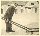
The 2 m long track bays with a track width of 600 mm consisted of rails that were connected at both ends by metal tie rods and rested on wooden sleepers. A man could bear a yoke with ease. The yokes were connected by unusually shaped, diagonally offset, self-locking Dolberg straps so that the yokes fit together at both ends and, thanks to their mobility, can easily be adapted to any uneven terrain. The tabs held the joints tightly together without screwing. But they were prepared with holes for screwing together if the tracks were to remain on one line for a long time.
Arched yokes were bent in a radius of 4 m. They were only 1.5 m long and could be used for right and left turns. The easy disassembly allowed wagons to pass quickly by simply lifting out a yoke or two.
The 4 m long Spalding universal switch was provided with so-called forced rails as wheel guides on the adjusting device , which should make it impossible to derail, even if the switch was incorrectly set. By simply unscrewing it from the base and then turning it, a right turnout could be converted into a left turnout and vice versa, as the double-headed rails used for the turnouts had the same profile above and below.
Easy and safe to use turntables with connecting rails were used for bends at right angles. The turntable could be locked after each turn with a light lever.
dare
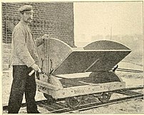
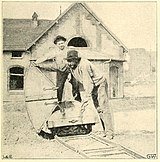
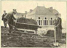
The tipping lorries had double flanged wheels and were very handy. The contents fell so far off the track that the track was always free. When tipping, the entire contents slid out of the trough without having to shovel a large part out by hand, as with other systems. The underframe of the tilting trolley could be used as a flat trolley for transporting piece goods without the arched attachments at both ends, which were held in place by a pin provided with screws.
The cars were available with or without a brake, as required. The brake was a lever brake that acted simultaneously and evenly on all four wheels, which quickly brought the car to a standstill with a handle or pull. In the case of cars without brakes, a simple brake stick was sufficient even on steeply sloping terrain. The wagons were unusually light. The dead weight of a wagon was 200 kg, while an iron wagon with the same size and load capacity weighed twice as much, so the workers always had to move an additional 200 kg dead load.
The undercarriage, as well as the tipping boxes, were made of the best pine wood and were built so simply that any blacksmith and carpenter could easily repair any damage.
Experience report from an Aachen landscape gardener
W. Kiehl, a garden technician from Aachen successfully tested the field railway operation with the Spaldingbahn since the beginning of 1903 in a horticultural company. He was able to lay a stretch of 250 m over uneven terrain with three men in three hours, with the individual yokes having to be brought together from different places. He did not use any screws to connect the rail yokes, partly because they were not part of the scope of delivery.
The whole rolling and lying material was made so solid that, if not caused by the carelessness of the workers, repairs were only very rarely necessary. During a whole year in which the railway was in operation every day, no repairs that would have caused particular costs were necessary in the Aachen operation. W. Kiehl warmly recommended this path to every landscaper who had to do earthworks. He will soon see how much cheaper and easier it is to work with this system that has arisen from practice for practice.
Sugar beet railway near Wesselburen

From the Osterhof station on the Wesselburen - Büsum ( Westbahn ) railway , a 2500 m long Spalding railway with a 600 mm gauge, laid in 1883, led to the Osterhof estate of the Wesselburen sugar manufacturer near Büsum. Around 1883 up to 300 tons (6000 quintals) of sugar beets were carried on it every day. The bogie cars on this line had four axles with double- flanged wheels and a load capacity of 3 t (60 quintals). Two cars are still preserved in the Frankfurt Feldbahnmuseum , one of them with the original bogies with double flange wheels.
Cost use Bill
According to a report in the newspaper of the Association of German Railway Administrations, the running track cost 5 marks per meter in 1883 , the other equipment costs , wagons and the like around 5,000 marks, so that the procurement of a 3,000-meter-long line required 20,000 marks. On such a track, which was set up on Count H.'s estate, 6 horses transported around 3200 t (64,000 hundredweight) of beets in 40 days. Since an ordinary team of four would carry 6¼ t (125 quintals) a day, it would have taken 12½ to do the same work in the same time. 11 teams of four were thus saved, and since each team of four would have cost 10 marks on each of the 40 working days, the total savings through the field railway in one campaign amounted to 4400 marks or 22% of the total investment capital.
In 1886, around 20 marks per kilometer were estimated for laying as a forest railway.
Differences compared to the Decauville Railway
The main differences compared to the Decauville Railway were:
- Standard length of the track sections 2 m instead of 5 m
- Universal turnouts with double-headed rails instead of vignole rails
- Tilting lorries made of pine instead of metal
- Double flanged wheels instead of ordinary railway wheels
- Rails are screwed to wooden sleepers instead of permanently riveted to steel sleepers
- Self-locking on the rail joints
Patent specification
- HA Spalding in Jahnkow near Langenfelde (Pomerania): Innovations in transportable railways or field railways. Patent specification N ° 28074 from July 24th 1884 of the Imperial Patent Office.
Individual evidence
- ↑ Eduard Spalding: History of the German branch of the Spalding family. 1898.
- ^ Report on the XLIII. General - Assembly of the Natural History Association of the Prussian Rhineland, Westphalia and the Reg.-Bez. Osnabrück on June 14th, 15th and 16th, 1886 in Aachen.
- ↑ a b E. A. Paragraph: About field railways. In: E. Schrödter and W. Beumer: Zeitschrift für das Eisenhüttenwesen. Volume 12, No. 8, Commissionsverlag by A. Bagel, Düsseldorf, April 15, 1892
- ↑ a b Victor Freiherr von Röll: Enzyklopädie des Eisenbahnwesens, Volume 5. Berlin, Vienna 1914, pp. 42–54.
- ^ A b Victor Freiherr von Röll: Encyclopedia of the railway system. Second edition, Volume 5, Urban & Schwarzenberg, Berlin, 1914, p. 48.
- ↑ a b c W. Kiehl: Feldbahnbetrieb with the Spaldingbahn. (Here are eight illustrations by the author). In: The garden world. Illustrated weekly newspaper for all horticulture. Volume IX, February 25, 1905, No. 22. Pages 257–262.
- ↑ a b Victor Tilschkert: The Verpflegsnachschub in the war on the portable field railway and report on the field railway exhibition in Lundenburg in August 1886. In: kk Technical & Administrative Military Comité: communications on matters of artillery and genius-being. 18th year, 1887. pp. 481-489.
- ^ Short messages from the BD Hamburg. . October 17, 1883.
- ^ Adolf Runnebaum: The forest railways. Springer-Verlag, 1886. p. 3.


