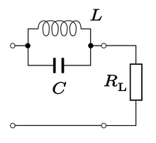
Trap circuit
In electrical engineering , a blocking circuit is an arrangement that blocks a certain frequency of an electrical oscillation because its resistance is particularly high here. It can be implemented using a parallel resonant circuit that is connected to the signal line.
General
The blocking frequency follows from Thomson's oscillation equation and is:
Here f is the blocking frequency, L is the inductance of the coil and C is the capacitance of the capacitor , the oscillating circuit is in resonance .
For this frequency f , the complex alternating current resistances of coil ( ) and capacitor ( ) are of the same magnitude, but have different signs in the imaginary part .
with the angular frequency .
This means that the currents in the capacitor and coil branches are equal and run anti- parallel. Outwardly, they cancel each other out, from which the high resistance results. or at f res is the characteristic resistance of the resonant circuit. The lower it is compared to the impedance of the signal line, the more selective or narrower the blocking effect. This is because its attenuation by the line impedance is then lower.
Since resonant circuits with a low characteristic resistance can only be implemented with a lower quality than those with a high characteristic resistance, inductive coupling is often used, which also makes it easier to maintain the line impedance outside the blocking range.
Applications
Interference suppression
In an antenna cable or in the antenna wire of a wire antenna, electromagnetic waves induce a mixture of alternating currents of different frequencies and amplitudes. If you are interested in receiving a weak transmitter, next to whose frequency there is a strong transmitter, you connect a blocking circuit in the antenna line that is tuned to the frequency of the strong transmitter. The trap circuit is low-ohmic at all frequencies outside its resonance frequency and allows them to pass. Only at and in the immediate vicinity of its resonance frequency does it act like a high-ohm resistor and the transmitter interfering with the receiving device is blocked. In the GDR, for example, it was helpful to block strong local channels or GSSD channels, depending on the location , in order to be able to receive West TV or West German VHF channels. Also offered today, such trap circuits serve to attenuate one or more VHF channels on which a strong transmission signal is present.
Multi-band antennas
Another example for the application of blocking circuits is the use of wire antennas for a plurality of frequency bands, for example, at a dipole antenna as shown in the drawing on: In this case, in the dipole are the antenna at certain locations blocking circuits ( English trap s) incorporated, which the resonance-length Determine l 1 for the higher frequency band. In this way, the antenna for the higher frequency "ends" at this point in the trap circuit.
In the second, lower frequency band, the trap circuit acts inductively, so that the antenna is electrically lengthened or mechanically shortened and the total length of the antenna, consisting of the length l 1 + l 2, can be optimized for this low band. In this way, antennas that can be used by radio amateurs in particular for several amateur bands are realized, for example the W3DZZ dipole antenna and the various modifications of this basic design.
Telephone system
In the past, in analog, wired telephone networks, the so-called POTS , charge indicators were used as an additional function , which were controlled by counting pulses transmitted in parallel with the voice. Each counting pulse was an oscillation lasting 150 ms, for example 16 kHz in Germany or 12 kHz in Switzerland and Austria were used, which were passed through a suction circuit to the counter and made inaudible to the telephone subscriber by a blocking circuit.
literature
- Alois Krischke , Karl Rothammel : Rothammels Antennenbuch . 13th edition DARC-Verlag, Baunatal 2014, ISBN 978-3-88692-065-5 (EA Neuenhagen 1959)
swell
- ↑ http://www.qsl.net/dl7jv/trap.htm Wire antenna with 4 trap circuits for 5 frequency bands
- ↑ Transmission of the counting impulses on the telephone


