Breadboard
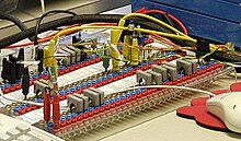
A plug-in board ( English breadboard ), also called "breadboard", "breadboard" or "Protoboard", the mechanical fastening and electrical connection of used electronic components for experimental circuits and experiments.
The English term English breadboard (dt. Breadboard) is derived from it from that electronic circuits have been used to love built on wooden boards. Tacks were sometimes used to fix connecting wires or solder components to them.

In contrast to printed circuit boards , the components of breadboard are not soldered but plugged into spring contacts . This allows the circuit to be changed by simply plugging it in. Breadboards are often used in the hobby area and sometimes also in schools / training, as the assembly is quick and no soldering is required. Similar plug-in systems are mostly used in electronics experiment kits.
An alternative to the breadboard are breadboard boards on which electrical circuits can be flexibly soldered.
Typical specifications
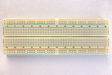
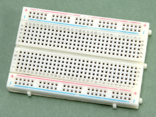
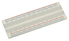
A breadboard usually consists of a plastic plate in which there are a number of contact springs (nickel-plated [standard], tin-plated or gold-plated). The distance between the contact springs is usually 0.1 inch (2.54 mm) so that integrated circuits (ICs) with DIL housing can be plugged directly onto the breadboard. The maximum current carrying capacity of the contact springs is typically 1 ampere, the permissible diameter of the component connections 0.3 to 0.8 mm (corresponding to AWG 20–28). Most breadboards are 85 mm high.
The contacts are usually arranged in two opposite parallel rows of 5 slots each. The distance between the two rows is 7.62 mm (0.3 inch). Often one or two rows of contacts run across the edge. Although these are arranged in groups of 5, they are all connected to one another. Only with longer boards are the transverse rows mostly interrupted at half their length. These cross connections are mostly used to distribute supply voltage and ground .
variants
The table shows the commercially available variants. There is no uniform type designation - just common names.
| Type | Length [mm] | Width (mm] | Number of pins in the middle area | Number of pins supply | Number of rows in the middle area (2 × 5) | particularities | image | |
|---|---|---|---|---|---|---|---|---|
| EB03-2P | 165 | 11 | 0 | 2 × 50 | 0 | Pure supply bar as a supplement, 2 rows (red / blue), interrupted at half the length |
|
|
| EB03-1S | 165 | 35 | 630 | 0 | 63 | Only middle area without supply bar (dockable) | ||
| EB03-1S1P | 165 | 45 | 630 | 2 × 50 | 63 | Central area with a supply bar | ||
| EB03 | 165 | 54 | 630 | 4 × 50 | 63 | Central area with two supply strips that are interrupted on half the length. The pins of the supply strips are offset by half the pin spacing (1.27 mm) to those in the middle area. Quasi-standard size | ||
| EB05 | 174 | 66 | 640 | 4 × 50 | 64 | The pins of the supply strips are parallel to those in the middle area | ||
| EB04 | 174 | 66 | 640 | 4 × 50 | 64 | The pins of the supply strips are parallel to those in the middle area, without (colored) imprint. | ||
| EB04-2P | 174 | 15th | 0 | 4 × 50 | 0 | Pure supply bar, without (colored) imprint | ||
| EB04-1S | 174 | 42 | 640 | 0 | 64 | Only middle area without supply bar, without (colored) imprint | ||
| EB04-1S1P | 174 | 55 | 640 | 2 × 50 | 64 | Central area with a supply bar | ||
| EB02-2P | 82 | 95 | 0 | 2 × 25 | 0 | Pure supply bar as a supplement, 2 rows (red / blue) | ||
| EB02 | 82 | 55 | 300 | 4 × 25 | 30th | Central area with two supply strips. The pins of the supply strips are offset by half the pin spacing (1.27 mm) to those in the middle area. Half standard size | ||
| EB06 BB-301 |
84 | 45 | 230 | 2 × 20 | 23 | Central area with a single, continuous supply bar, the pins of the supply bars are parallel to those in the central area, without (colored) imprint, the supply bars cannot be separated, 4 fastening holes, docking system: locking lugs | ||
| EB01 SYB-170 |
45 | 35 | 170 | 0 | 17th | Only middle area, available in various colors, alternative name: "Mini" | ||
| EB08 SYB-46 |
90 | 52 | 230 | 2 × 20 | 23 | Middle area with a single, continuous supply strip, the pins of the supply strips are parallel to those in the middle area, without (colored) imprint, the supply strips cannot be separated, 4 fastening holes, docking system: tongue and groove, slightly larger than EB06 | ||
| EB07 SYB-120P |
177 | 46 | 600 | 2 × 50 | 60 | Middle area with a single, continuous supply strip, the pins of the supply strips are parallel to those in the middle area, without (colored) imprint, the supply strips cannot be separated, 4 fastening holes, cannot be aligned | ||
| XF-25 | 50 | 0 | 5 | "Ultra-Mini", 2 knobs on the floor, compatible with Lego , available in various colors, cannot be lined up | ||||
| MB-102 | 165 | 85 | 630 | 4 × 50 | 63 | Central area with two continuous supply strips. The pins of the supply strips are offset by half the pin spacing (1.27 mm) to those in the middle area. |
Connecting lines

The connection between the various electrical networks is established by the wired components themselves. If that is not enough, because, for example, longer distances on the breadboard have to be bridged, connections can be made using cables. Solid wires are suitable for interconnection, flexible wires ( strands ) cannot be plugged into the contacts. You can easily make these connecting lines yourself from commercially available insulated wires. With bare wires, there is a risk of short circuits in the circuit structure if two wires touch.
If, despite this, flexible lines have to be used for the construction, it is advisable to solder a contact pin to the line.
If bare copper wires are used without any further surface treatment, there is a risk that corrosion (formation of copper oxide) will occur over time. With increasing layer thickness, the electrical contact resistance between the contact clamp and the wire increases. In unfavorable cases this can lead to the circuit not functioning. If, however, tinned copper wires are used, this effect does not occur.
Use of SMD components
There are special adapter boards available for SMD components . These have solder pads for the SMD components and additional solder connections with holes for contact pins. These can then be plugged into the contact springs on the plug-in board.
restrictions
Due to parasitic capacitances and relatively high, non-reproducible contact resistance at the contact springs, the use range of plug-in boards to smaller circuits with low frequencies (typically <10 MHz) limited. Circuits with a large number of components quickly become confusing due to the large number of jumpers required. Only wired components and ICs in DIL housings can be used on a breadboard . The use of SMD components or ICs with other housing shapes is only possible with adapters. In the case of experimental set-ups with higher voltages, it must be ensured that there is no voltage flashover between adjacent rows of contacts. The same applies to components and lines in outdoor wiring. The maximum current per contact point is also limited. The heat dissipation is very low compared to structures with printed circuit boards in breadboards, which can locally lead to a significant increase in the component temperature.
Optical experimental panels
In the field of optics , the term breadboard refers to a plate, often with a grid of threaded holes , on which optical experiments are set up and carried out. Such breadboards are made of aluminum, steel or stone. If the sensitivity to vibrations is high, there is often an external vibration damping.
Optical structures require high rigidity and thermal stability of the planarity of the plate; this is achieved in part through the use of Invar steel and a sandwich construction of such panels.
For very large structures, the larger optical tables are used instead of breadboards , which normally also have vibration damping integrated.


