
Impulse switch

.png)

Impulse switches are electromagnetically operated switches ( relays ) that change their switching status when an electrical pulse is received. In typical use, it is connected to several buttons with which it can switch a common consumer on and off, for example the light in the hallway .
The following terms are also used for impulse switches: impulse switches, (installation) remote switches, Eltako, impulse relays, step switches or step relays. The last two terms can also designate devices with more than two switching states. The widespread device with only two switching states ( off and on ) is a kind of bistable relay .
The brand Eltako (for el ektrischer Ta st ko ntakt) of 1949 developed latching relay became the generic brand name .
Code letter
Identification of equipment according to IEC 81346 2010: 05 is Q .
Layout and function
The electromechanical impulse switch is a switching relay, which contains a mechanism between the armature of the electromagnet and the working contact (s) (in the example in the picture consisting of a combination of cam and pawl ), which causes it to change its switching status with each actuation and until the next Operation maintains. The functional equivalent in digital technology is the asynchronous T flip-flop .
In electrical installation , impulse switches are used in impulse switching instead of off , toggle and cross switches when several switching points are to switch the same consumer (e.g. light), for example in hallways . The wiring of the impulse circuit is simpler and usually cheaper. The wiring is identical to that of the staircase light timer . In addition to simple impulse switches with two switching states, there are also impulse series switches with two contacts that have three or four switching states ( off, one circuit on, another circuit on and, if necessary, both circuits on; see series connection and group switch ). There are also combinations of timer and current impulse functions, in which the consumer is switched off automatically after a certain time.
Impulse switches are available in two designs: for installation in 70 mm junction boxes and for mounting on mounting rails (top hat rails) in a sub-distribution . So were z. B. provided many prefabricated housing in the area of the GDR with mechanical impulse switches with 12 V operating voltage and mounting rail mounting. This enabled the installation for actuation to be carried out with a material- saving bell line . All that was needed was a 12 V transformer to feed all residential units on one staircase.
Common electromechanical impulse switches are designed for a coil voltage of 12 or 24 V DC and AC voltage or 230 V AC voltage. Electronically controlled versions enable a universal control input with, for example, 8 to 230 V. Electronic impulse switches, which work with monostable switching relays, constantly require some electrical energy. There are, however, electronic impulse switch without standby manufactured Loss. They work with bistable switching relays. This technology helps to practically avoid heating and personal consumption .
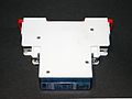
Impulse switch for top hat rail mounting
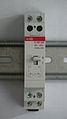
Impulse switch on top hat rail (unwired) with switchover option


Specialist literature
- Günter Springer: Expertise in electrical engineering. 23rd edition, Verlag Europa-Lehrmittel, Wuppertal, 1989, ISBN 978-3-8085-3219-5 .
- Ernst Hörnemann, Heinrich Hübscher: Electrical engineering specialist training in industrial electronics. 1st edition. Westermann Schulbuchverlag GmbH, Braunschweig, 1998, ISBN 3-14-221730-4 .
Individual evidence
- ↑ Company history Eltako electronics
- ↑ Description of the multifunction impulse switching relay ESR61M-UC
- ↑ Remote switch Stella
- ↑ a b https://www.eltako.com/fileadmin/downloads/de/datenblatt/Datenblatt_ES12-110-UC.pdf Documentation of the impulse switch ES12-110 from the company / brand ELTAKO, accessed on December 7, 2017