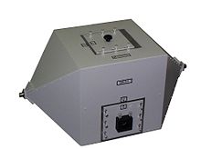
TEM cell
A TEM cell ( T ransverse E lectro m agnetic Cell) provides a defined environment for tests and measurements in the art of electromagnetic compatibility. The TEM cell is used to hold the measuring or test objects during the measurement and testing of radiated emitted interference or interference immunity .
TEM cells are used in the field of electromagnetic compatibility for EMC measurements and EMC tests . They provide a measurement environment to record interference immunity or interference emissions so that, for example, the requirements of the European directive on electromagnetic compatibility and the standards harmonized with it can be checked. The coaxial shape and the resulting operation in TEM mode ensure that a field wave resistance of approximately 377 ohms occurs when the test volume is applied. A TEM cell can, depending on its size, be operated in the frequency range from 0 Hz to a few 100 MHz in TEM mode .
Since the TEM cell shields its test volume completely closed, the test volume is electromagnetically decoupled from the external environment. A TEM cell can therefore be operated in normal rooms without having to pay attention to the special equipment of these laboratory rooms. For manufacturers of smaller products, this cell has an advantage due to its compact size compared to measurements in absorber rooms, which have a considerably larger space requirement.
Compared to a GTEM cell , the TEM cell with a similar size has a narrower usable frequency band. In contrast to the GTEM cell, it has two connections and can therefore also be used to determine scattering parameters and continuity tests.
Structure of a TEM cell
The TEM cell consists of three parts. These are the conical feed part, the middle part with the test volume and the output part opposite the feed part, which also converges conically. Inside there is a centrally arranged plate (the septum) as an inner conductor, so that a coaxial conductor structure results.
The TEM cell has a connection for a coaxial supply line at each of its two tips . Starting from the connection of the feed, it expands. The inner conductor of the coaxial connection merges continuously into the septum arranged centrally over the cross section, namely the inner conductor of the TEM cell. The outer conductor goes continuously from the connection point into the outer conductor of the TEM cell. The conical feed and the end part have the same structure in accordance with the symmetry of the TEM cell.
The outer conductor of the TEM cell has a rectangular cross section. Inside the cell, the flat septum is arranged in the center of the cross-section in such a way that a line impedance of 50 ohms results , which is maintained over the length of the TEM cell. It is chosen so that common laboratory measuring or testing devices with lines with a characteristic impedance of 50 ohms can also be operated reflection-free at the connection of the cell in its useful frequency band.
The adaptation to the characteristic impedance of the vacuum of ~ 377 ohms is ensured in this arrangement by the fact that a transverse electromagnetic field spreads in the dielectric air within the TEM cell. The wave resistance of 50 ohms is linked to the free space wave resistance via the geometric shape of the inner conductor and outer structure of the TEM cell. The article Wave impedance describes the definitions of line impedance and free space wave impedance and the basic relationship between the two quantities . Waveguide waves , that is, modes of a higher order, develop in the TEM cell, depending on their size, at a few 100 MHz. In the case of the GTEM cell , this is typically only the case in the gigahertz range with a comparable size. In this respect, the GTEM cell is superior to the TEM cell with comparable dimensions in terms of the usable frequency range for far field conditions.
Immunity tests with a TEM cell
For immunity tests, an electrical signal that is applied to the connection of a TEM cell leads to currents and voltages in the septum and outer conductor structure. This creates a field between the septum and the shell of the TEM cell against which electronic devices can be tested.
Interference emission measurements with a TEM cell
The TEM cell can also be used to measure field-related emissions from devices. The interference emissions (electrical, magnetic or electromagnetic fields) of a test object in the TEM cell generate currents and voltages in the septum and shell. These currents and voltages can be picked up by a suitable measuring device (for example a spectrum analyzer or a measuring receiver ) at the connection of the cell and made available for further processing.
Web links
- Practical trial Introduction to the EMC University of Dortmund, Chair for High Voltage Technology and Electrical Systems, Dirk Peier, p. 12 (PDF; 1.71 MB)
- Data sheet of a Crawford TEM cell (PDF; 102 kB)
