Dividing apparatus

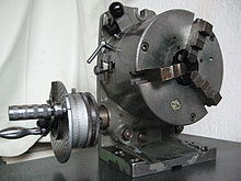
A dividing head is a device for precisely angular positioning of workpieces for machining on machine tools .
use
A dividing attachment is used in machining to machine a workpiece at certain angular positions. With the help of a dividing attachment, machining operations such as drilling patterns can be carried out, for example drilling on a full circle also distributed unevenly, but reproducibly.
Radial machining such as multiple grooves can also be made on a shaft (example: two keyways on a shaft offset by 120 °).
Another area of application is the production of regular profiles such as splined shaft profiles and gear teeth.
construction
The main body is usually made of gray cast iron and has at least one precisely aligned surface for clamping the dividing apparatus on the table of the machine tool. The base body accommodates both the table top and the gearbox to drive it. In the case of smaller dividing units, there are often two clamping surfaces at right angles to each other, which allow the axis to be aligned horizontally or vertically. Swiveling constructions are also common, so that swiveling of the milling head can be avoided when used on milling machines.
Grooves for fastening clamping devices such as three-jaw chucks are usually incorporated into the table top. Often there is a central bore with a Morse taper, which enables the simple change of smaller clamping devices such as drill chucks or collet chucks.
Simple dividing attachments consist of a base plate and a rotating dividing plate on it, which is positioned in certain angular positions by simple detents. Usually only a few, fixed, predetermined detents are possible.
With most dividing heads for setting (almost) any angle, the dividing plate is attached to a worm wheel. This is driven by a worm ( worm gear ), which in turn is turned manually using a hand crank or an electric motor.
A dividing head can be driven by hand and is then mostly used on conventional machine tools .
With an electromotive drive, the dividing head can usually be easily integrated into the CNC control of a machine, so that automatic processes are possible. This is of great advantage especially when manufacturing profiles with many pitches.
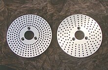
To create divisions with a hand-held dividing device, the hand crank is locked in the recesses of a perforated disc . The perforated disks have a certain number of equidistant bores that are arranged in a circle. Depending on their number, different, not just regular, pitches can be produced. Perforated disks usually have several pitch circles, which can be achieved using different radii on the same disk.
If the crank does not have to be turned a full turn to reach a partial position, but for example 2 full turns and 20 holes on the 30 hole circle, you can use the so-called "scissors". This consists of two pointers that can be rotated around the crank and are set so that the first pointer rests on the flank of the locked index pin. The second leg is then set to 20 locking holes in the direction of rotation. This aid avoids the error-prone counting of the index holes and thus ensures process reliability.
Part worm gears often have some play . Dividing heads have a clamping device to reduce this.
Application example
A gear with 31 teeth is to be produced with the aid of a dividing apparatus.
- With the dividing head used, 180 full turns of the crank are required to turn the table by one full turn of 360 ° (1 turn of the crank = 2 ° turn of the table).
- For 31 divisions, the table must therefore be rotated by ( 360 ° ⁄ 31 = 11 19 ⁄ 31 °) ≈ 11.613 degrees for each division .
- This requires (11 19 ⁄ 31 ° / 360 ° * 180 = 5 25 ⁄ 31 ) ≈ 5.806 turns of the crank.
- If the calculation is decimal instead of the correct fraction calculation, rounding errors are unavoidable. Then a table belonging to the dividing head is used to determine which bolt circle is suitable for the desired division. The calculation of fractions results in a bolt circle with 31 holes (since 31 is a prime number ).
- The table shows that 5 complete turns of the crank and an additional 25 holes on the 31 hole circle are necessary for a division.
- The dividing scissors are adjusted so that one leg rests on the latched bolt, the other one points to the 25th hole in the direction of rotation.


