Transformer switching relay
An inrush current limiter (also transformer relays , TSRL ) or a Transformatorsanfteinschalter also Trafosanfteinschalter , is an electronic assembly that the increased inrush current at power of a transformer with an iron core avoids. It also serves as a relay for switching the transformer on and off and has a control input for this purpose.
Basics
When using a transformer switching relay or transformer soft switch, no increased inrush current flows when a transformer is switched on. This is achieved in that the transformer core is premagnetized for a short time before switching on by means of small, unipolar voltage-time areas and then fully switched on in antiphase at a suitable point in time. The magnetization of the iron core is brought to the normal operating reversal point of induction B on the hysteresis curve with the premagnetization and then fully switched on.
The cause of the increased inrush current of a transformer is its remanence (residual magnetization) as well as the unsuitable switch-on time: If this is at the beginning of a voltage half-wave and the direction of voltage increase also coincides with the direction of the residual magnetization, the iron core gets into magnetic saturation, so that the current during the voltage half-wave increases sharply. (In this case, the voltage-time area of a half-wave cannot magnetize the iron core any further!) The resulting asymmetrical magnetization is only reduced in the course of several full waves via the copper resistance of the primary winding and the internal resistance of the network.
In the case of iron saturation, the inrush current is only limited by the internal resistance of the system and the resistance of the transformer primary winding. The inrush current is therefore particularly high in low-loss transformers. Transformers with low no-load currents and low iron losses also retain a particularly high remanent induction after switching off, which in turn is partly responsible for the high inrush current. The inrush current can reach up to 80 times the rated current. Without a transformer switching relay or inrush current limiters, the current surge can only be controlled with slow-acting fuses that are too large in terms of rated current , which often trigger the higher-level protective device or cannot adequately protect the transformer.
Layout and function
Transformer switching relays consist of a semiconductor switch ( triac ) with control and a mechanical relay that bridges the semiconductor switch after the switch-on phase.
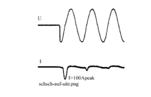
Conventional and well-known soft start devices simply dim up with a bipolar phase control starting from small to large current flow angles until the load is operated with full mains voltage. No-load transformers with low losses in particular have difficulties with this dimming, because due to the low no-load currents, the actuator, triac, thyristor cannot lock symmetrically to the holding current, then form a voltage-time area overweight on one side (voltage-time area = temporally integrated voltage curve, which the magnetic flux) and drive the transformer to saturation. The transformer switching relay, on the other hand, only works with unipolar voltage-time areas and thus enforces regular no-load currents from the start, as the graphic opposite shows.
The premagnetization and remanence of the transformer core is brought in one direction at the start of switch-on by pulses of only one polarity (see picture: voltage curve at the beginning). After a predetermined number of pulses or when the beginning of saturation is detected, the transformer is fully switched on at the beginning of an oppositely directed voltage half-wave (sinusoidal voltage curve in the picture above). Both are coordinated by a control that detects the zero crossings of the mains voltage.
The picture opposite describes the TSR switch-on procedure and also shows the magnetic flux. The measured transformer has a remanence of −0.95 T at the beginning. The individual unipolar voltage-time areas transport the magnetic flux step by step to the end point of the hysteresis curve. Then it is fully switched on and so the inrush current is not only limited, but a current surge is completely avoided. Noteworthy is the behavior of the magnetic flux, recognizable by the curve of the flux density B . When the positive maximum remanence is reached, the magnetic flux is moved from the next voltage time area to the end point of the hysteresis curve and then the magnetic flux falls back to the positive maximum remanence during the pause. The iron core therefore first reacts within the remanence limits in an integrating manner for the stress-time areas, in that the magnetic flux increases after each individual unipolar stress-time area, from the maximum remanence the integration effect ceases and the core now acts like a magnetic spring. After full switch-on, the current mainly shows the active current of the R load , which is in phase with the mains voltage. In the first half-waves after full switch-on, the slightly increased no-load reactive current rises above the voltage zero crossing because the transformer has been premagnetized a little too much.
As a result, the transformer core is initially pre-magnetized in one direction so that it can subsequently be fully controlled in the opposite direction when the voltage is switched on, without going into saturation. The voltage-time area width required for correct premagnetization only needs to be adapted once to the transformer type, the core air gap or residual air gap, for which a potentiometer, trimmer, is used. The process works completely independently of the load.
After the switch-on cycle has been completed, the triac is bridged with a relay contact in order to avoid its heat loss during further operation and to increase the short-circuit strength.
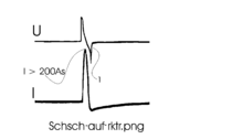
A switch-on process of the same transformer as used in the picture above, but switched on with a peak switch, can be seen in the picture opposite. The current peak would be even greater when switched on at zero crossing.
If a toroidal transformer is switched on with a peak switch, a fuse may blow, as can be seen in the adjacent picture. The peak activation process is only suitable for transformers with low or zero remanence, as is only the case with transformers with a significant air gap in the iron core.
application
Typical properties of application areas for transformer switching relays are:
- Frequent power cycling is required.
- Increased reliability without unintentional triggering of the fuse (security of supply) is required.
- On the primary side of the transformer, the nominal current should be fused.
- Upstream fuse elements, for example on the building side, must not trigger when the transformer is switched on.
- Saving of cable cross-section for longer cables to the transformer while maintaining the selectivity of the fuses.
- An energy-saving transformer with high efficiency and therefore inevitably a high inrush current should be used.
- A transformer is located in a closed housing with no cooling air supply and must therefore only generate little heat and therefore has a high inrush current without its limitation.
- With the special "slow dimming" design, a transformer switching relay can also switch on several switched-mode power supplies together, including those with power factor correction, so that the 16 A B building protection is not triggered. Otherwise this fuse usually triggers when more than two 50 watt switched-mode power supplies are switched on. The attenuation of the current peaks is more than a factor of 10. Computers, screens, laptops, industrial controls can be gently switched on behind a selective protection, which is arranged, for example, after a UPS (uninterruptible power supply),
Examples are isolating transformers in endoscopy trolleys or in traffic lights with LED signal lights. In many vehicles with power supply, such as those of broadcasting corporations and the technical relief organization , there are transformer switching relays in front of the isolating transformers. Low-voltage heating devices that are fed via transformers can be switched on and off at rapid intervals with the transformer switching relay in front of the transformer, in a special design without a bypass relay, so that the heating energy can be precisely dosed.
Transformer switching relays are particularly suitable for toroidal and sectional band core transformers , as they work with a high magnetic flux density close to the onset of saturation . These core designs use textured core sheet, in which the Weiss areas can be aligned particularly easily using the magnetic flux. Toroidal transformers also do not have a technologically conditioned air gap and therefore have a high level of remanence in the iron core, and when they are switched on they saturate the entire core particularly quickly without any inrush current limitation.
Transformer switching relays can also switch three-phase transformers without inrush currents or cycle in rapid succession.
Advantages and disadvantages
Transformer switching relays have the advantage over inrush current limiters that consist of an NTC thermistor that they are immediately ready for the next switching process. H. do not require a cooling phase, and that they completely avoid the inrush overcurrent. Compared to other electronic soft starters , they have the advantage of a shorter starting phase and precise switching on of no-load transformers.
Transformer switching relays can also cope with the failure of only one half-wave of the supply network by switching them off immediately and on again at the right time without causing an inrush current. (The half-wave failure test is a test criterion for electrical medical devices.) Transformer switching relays can withstand a short circuit when properly protected. Transformers operated via transformer switching relays can be protected against the rated current with less slow fuses and are therefore better protected against overload. The temperature load on fuses, as occurs with inrush currents, is avoided, which increases their reliability and service life.
The disadvantage of transformer switching relays compared to thermistors, for example, is the higher component costs and consequently the price. So far, they have hardly been used in mass applications for private consumers. In other applications, the higher price may be acceptable and the benefits outweigh the benefits; for example with isolating transformers in medical devices and traffic light signal systems.
See also
Web links
- from Mechatronik 04.2010, switch on the switching power supply gently
- Switching on switching power supplies without inrush current


