
Automatic dialing device for data connections


An automatic dialing device for data connections ( AWD ) can automatically set up a modem connection without manual intervention by a person .
General
An AWD enables even telephone modems that are not capable of dialing to establish an automatic connection in the telephone network to any communication partner. This dialing device can be an independent device or a software function within a modem. Some modems before 1990 could be retrofitted with this option with an additional board. Such an add-on board cost an additional basic fee of DM 30 in 1982.
In the early days of computer technology in the mid-1950s, mainframe computers were often controlled via simple operating devices ( terminals ). The length of the connection between the terminal and the mainframe could usually only be a few dozen meters , depending on the interface used . A frequently used interface was described in the American RS 232 standard, often referred to as COMx on a commercially available PC . The International Telecommunication Union , however, recommended an interface according to V.24 with more interface lines and functions.
A dedicated line was used for greater distances, and a modem was used to convert the signals between the terminal and the mainframe . A modem was originally a simple device for transferring data between two fixed points. A dedicated line could not be switched to every terminal for home workstations or for the purpose of remote maintenance , or a terminal should be able to access different mainframes. An alternative connection option to the dedicated line was the dial-up line via the public telephone network, in which the connection is temporarily established and terminated by means of a dialing process.
The existing modems, however, were unable to establish connections on their own. In Germany, the desired connection was dialed manually by the user through a telephone, after reaching the modem of the remote terminal (recognizable by the answer tone of 2100 Hz) the telephone was disconnected from the line by pressing the data button and the modem was switched on. The modem took over further communication.
This manual connection establishment could be automated by an AWD . To do this, the device was looped into the connection line between the modem and the junction box and thus simulated a telephone with a data button. The establishment of a connection via an AWD was controlled by a separate interface.
Although originally not designed some had remote data switching devices and ISDN - terminal adapter interface an automatic dialer.
The biggest disadvantage of an AWD was the need for an additional interface, while alternatives (see below) transmitted the dialing information over the data lines.
An AWD should not be confused with a WAD ( automatic dialing machine for data connections ), which can only dial predefined phone numbers.
history
National (US)
International (CCITT)
The description of the processes of an AWD was published in 1968 by the CCITT (today's name ITU-T ) in Recommendation V.25 .
The necessary interface lines for an AWD were numbered consecutively from the number 200 within Recommendation V.24 (first version 1964); the interfaces required for data transmission start at the number 100. An AWD requires its own interface to establish a connection, mechanically it is a 25-pin ISO-2110 socket; the electrical values correspond to recommendation V.28 . The EIA-232 standard (formerly RS-232 ), which is widely used by the American business association Electronic Industries Alliance (EIA), does not have any functions for establishing connections.
The V.25 was revised around 1995, the outgoing automatic connection establishment was deleted without replacement.
The signaling of an automatically accepted modem connection by the answering tone of 2100 Hz still exists today.
The specialty of an AWD is the parallel coded transfer of the dialing characters on four interface lines at the same time, there are also separate lines for reactions of the switching network (called station connected / occupied etc.).
AWDs with parallel character transfer are no longer relevant today.
Interface lines used for V.24
The German standard DIN 66020-1 corresponds to V.24 from 1996. The connection control method of an AWD is described in DIN 66021-4.
| V.24 interfaces of the 200 series | |||||
|---|---|---|---|---|---|
| ITU | DIN | description | Contact ISO 2110 |
||
| ITU-T V.24 | DIN 66020-1 | ||||
| Earth line (return lines, earth connection) between data terminal equipment and AWD | |||||
| 201 | E22 | Signal ground or common return | Plant earth | 7th | |
| Transfer of dialing characters in the direction of an AWD | |||||
| 206 | W21 | Digit signal (2 0 ) | Select bit 1 | 14th | |
| 207 | W22 | Digit signal (2 1 ) | Select bit 2 | 15th | |
| 208 | W23 | Digit signal (2 2 ) | Select bit 3 | 16 | |
| 209 | W24 | Digit signal (2 3 ) | Select bit 4 | 17th | |
| Control lines in the direction of an AWD | |||||
| 202 | S21 | Call request | Occupy the transmission line | 4th | |
| 211 | S22 | Digit present | Accept dialing characters | 2 | |
| Reporting lines of an AWD | |||||
| 203 | M21 | Data line occupied | Transmission line busy | 22nd | |
| 210 | M22 | Present next digit | Readiness to accept dialing characters | 5 | |
| 205 | M23 | Abandon call | Choice unsuccessful | 3 | |
| 204 | M24 | Distant station connected | Called station switched on | 13 | |
| 213 | M25 | Power indication | Operational readiness | 6th | |
Parallel coding of the dialing characters
The bit combinations for dialing characters mentioned in V.24 were originally developed for establishing connections in the telephone network; they have been expanded for use in data networks. These additional characters are mentioned in ITU-T recommendation X.21bis (see also DIN 66244-2), which describes the use of synchronously operating data terminal equipment with V interfaces in public data networks. In Germany this was the Datex-L network.
The following special characters are available: "EON" (End of Number) ends the character transfer in the telephone network; in data networks it is the "+". The character “SEP” (separation) creates a pause of one second, which can be inserted into the dialing digits as often as required. The four other bit combinations are used in data networks.
There is no replica of an earth button for outside line access, which is why the use of an AWD on many older PBXs is not possible.
| Coding of the dialing characters; Interface designations above: ITU-T, below: DIN |
||||||||||||||
|---|---|---|---|---|---|---|---|---|---|---|---|---|---|---|
| Dialing characters |
209 W24 |
208 W23 |
207 W22 |
206 W21 |
Dialing characters |
209 W24 |
208 W23 |
207 W22 |
206 W21 |
Dialing characters |
209 W24 |
208 W23 |
207 W22 |
206 W21 |
| Dial characters for modems on analog telephone lines | Special characters for data networks | |||||||||||||
| 0 | 0 | 0 | 0 | 0 | 6th | 0 | 1 | 1 | 0 | + | 1 | 1 | 0 | 0 |
| 1 | 0 | 0 | 0 | 1 | 7th | 0 | 1 | 1 | 1 | , | 1 | 1 | 0 | 1 |
| 2 | 0 | 0 | 1 | 0 | 8th | 1 | 0 | 0 | 0 | / | 1 | 1 | 1 | 1 |
| 3 | 0 | 0 | 1 | 1 | 9 | 1 | 0 | 0 | 1 | . | 1 | 1 | 1 | 0 |
| 4th | 0 | 1 | 0 | 0 | EON | 1 | 1 | 0 | 0 | - | 1 | 0 | 1 | 0 |
| 5 | 0 | 1 | 0 | 1 | SEP | 1 | 1 | 0 | 1 | |||||
Sequence of an automatic connection establishment
The AWD reports its operational readiness with the message line M25; the data terminal equipment (DTE) monitors the message line M21 (telephone call or manually established data connection is active).
When a connection is requested, the DTE gives the command via the control line S21 to seize the transmission line and waits for the response from the AWD (M21, transmission line occupied).
- The AWD requests a dialing digit combination through the message line M22 in the ON state.
- The DTE creates this and gives the command to take over via the control line S22 in the ON state.
- The AWD switches off the message line M22 and dials this number; the DTE switches off its control line S22 in the meantime.
- Then the same sequence takes place up to the combination EON, which ends the transfer of the dialing digits.
After the election, the AWD sends an intermittent signal tone at 1300 Hz (0.5 s to 0.7 s duration, 1.5 s to 2 s pause) to signal the desired data transmission.
If within the next 10 s or 30 s, selected by the user using a toggle switch, an answer tone of 2100 Hz is received from the called modem, the connection has been established. The AWD simulates the pressing of a data key for modem connection and reports via the M24 interface that the called station is switched on.
Without an answer tone, the dialing attempt is aborted, the DTE receives a message via the M23 interface that the dialing was unsuccessful. The rest of the data transfer process is carried out by the terminals involved.
Alternatives to parallel character transfer
In 1984, the CCITT published Recommendation V.25bis, which, among other things, describes the function of an AWD not only for asynchronous , but also for character-synchronous (e.g. BSC ) and bit-synchronous (e.g. HDLC ) data transmissions and the serial interface lines for data transmission used.
Serial transfer of commands to modems existed before; The Hayes company had set a quasi-standard with its AT command set, which, however, did not correspond to any international standard. Other modem manufacturers copied this instruction set and used their own extensions.
Many of the original Hayes commands were described by the ITU-T from 1997 in Recommendation V.25ter (and additions); this was later renamed to V.250. Today the ITU-T numbers of V.250-V.299: Control procedures are reserved for general commands for the control of data transmission devices .
Since the V.25 or RS-366 required its own interface to establish a connection, there were converters. These converted the parallel selection commands into serial ones and could thus be looped directly into the data interface. The additional connection to establish the connection could thus be omitted.
photos

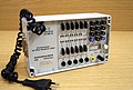
Modem with integrated AWD, with reference to the interfaces used and selector switch for the waiting time of the answer tone.

Remote data switching device DFG9600 UE-1 (above), rear side with interfaces for data transmission and to AWD.
The DFG UE-2 (below) has an X.21 interface which, in addition to data transmission, includes its own dialing procedure.
Remote data switching device NFGt64UE, rear
Test device of the Deutsche Bundespost, manufactured in the FZA Elmshorn


Individual evidence
- ↑ Modem 2400 DX, additional dialing AW24; Description of commissioning; Published by the Public Switching Systems division, Siemens Aktiengesellschaft; Order number: A22581-F102-A2-2-18; 8/85
- ↑ Plug-in, automatic selection device for a data transmission device ...
- ↑ AUTOMATIC ANSWERING EQUIPMENT AND / OR PARALLEL AUTOMATIC CALLING EQUIPMENT ON THE GENERAL SWITCHED TELEPHONE NETWORK INCLUDING PROCEDURES FOR DISABLING OF ECHO CONTROL DEVICES FOR BOTH MANUALLY AND AUTOMATICALLY ESTABLISHED CALLS downloading the version of recommendation V.25 in 1988, with the description of the recommendation V.25 by transferring the destination number in parallel
- ↑ LIST OF DEFINITIONS FOR INTERCHANGE CIRCUITS BETWEEN DATA TERMINAL EQUIPMENT (DTE) AND DATA CIRCUIT-TERMINATING EQUIPMENT (DCE) Download recommendation V.24 in the version from 1988
- ↑ AUTOMATIC ANSWERING EQUIPMENT AND GENERAL PROCEDURES FOR AUTOMATIC CALLING EQUIPMENT ON THE GENERAL SWITCHED TELEPHONE NETWORK INCLUDING PROCEDURES FOR DISABLING OF ECHO CONTROL DEVICES FOR BOTH MANUALLY AND AUTOMATICALLY ESTABLISHED CALLS. 25 in the selection of the version was removed by VALLS in 1996.
- ↑ ITU-T Recommendation V.25 bis: Automatic calling and / or answering equipment on the general switched telephone network (GSTN) using the 100-series interchange circuits. (Name of the 1993 recommendation)
- ↑ ITU-T Recommendation V.25 bis: Synchronous and asynchronous automatic dialing procedures on switched networks (description of the recommendation 1996)
- ↑ RS-366 to AT modem command converter & visa versa
literature
- CCITT Recommendations of the V-Series and the X-Series, Volume 1.1, Data Transmission over the Telephone Network, R. v. Decker's Verlag, G. Schenk GmbH, Heidelberg 1990, ISBN 3-7685-1190-1
- Hermann Gabler (Ed.): Text and data transmission technology, Volume 6 Telecommunications technology , R. v. Decker's Verlag, G. Schenk GmbH, Heidelberg 1988, ISBN 3-7685-2887-1