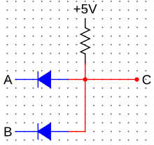
Wired AND operation
A wired-AND operation ( English for wired AND ), rarely phantom ANDing called, is used in the digital circuitry when two or more outputs are connected together so that the circuit as an AND gate (engl. AND ) works. Often no additional, active hardware is necessary for this link, because special configurations of the logic outputs are used, such as open collector or open drain outputs.
Generally, this type of logic operation is also called wired logic (or English. As wired logic called). Wired-OR technology is directly related to this circuit structure . In contrast to the wired-OR logic, the output transistors are activated high. The logic level can be tapped directly at the resistor. In contrast to the wired-OR operation, the wired-AND operation does not require a negation of the output signal.
The wired-AND operation can be in a positive digital logic (logic state 1 corresponds approximately to the positive supply voltage) in the simplest case by diodes reach their cathodes are used as inputs, as in the illustration, the terminals A and B . The interconnected and, via a resistor lying in the supply voltage anodes produce at the output C only a logical 1 on the output if all inputs are also logic 1 is applied.
Another circuit variant in positive digital logic uses open-drain outputs for field effect transistors and open-collector outputs for bipolar transistors, which are also connected to the supply voltage via a resistor. If all transistors in these outputs are blocked (logical 1 ), the output also has 1 , which corresponds to the logical AND function.
The wired AND operation is similar to the wired OR operation, which forms a logical OR gate . By using non-gates and applying De Morgan's laws , these two variants can be converted into one another.
The application of the wired AND link extends to the areas of digital components in standard technology, digital components in ECL technology and analog comparators with digital switching outputs. The description of the applications in the three technologies can be found under Wired-OR technology.
When the programmable logic controller (PLC) came onto the market, encoders were sometimes wired in series or in parallel in order to save (expensive) input cards. Such links are called phantom AND or phantom OR. These are neither documented nor recognizable in the program. Today this type of interconnection is no longer used, as PLCs are available with a sufficient number of logical inputs and outputs.
literature
- Ulrich Tietze, Cristoph Schenk: Semiconductor circuit technology . 12th edition. Springer, 2002, ISBN 3-540-42849-6 .
- Klaus Beuth: Digital technology . 10th edition. Vogel, 1998, ISBN 3-8023-1755-6 .
- Manfred Seifart, Helmut Beikirch: Digital circuits . 5th edition. Technology, 1998, ISBN 3-341-01198-6 .
