Absorber chamber

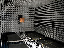
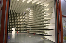
In EMC testing technology, an absorber chamber is a defined environment, on whose metallic, electrically conductive walls inside absorbers for electromagnetic waves are attached. The absorber chamber differs from the anechoic rooms customary in acoustics in that the absorbers on their walls are able to absorb electromagnetic waves and not just sound waves .
construction
Outside, the test chamber consists of metallic and electrically conductive walls that shield the interior of the chamber from the outside world. The shielding attenuation that can be achieved is different depending on the chamber and in the range of 60 dB to 90 dB. In the construction of the chamber, there is the difficulty of making all openings for supply and discharge lines such as ventilation, lighting, electrical lead-throughs and the doors for access to the chamber HF-tight and preventing unwanted slot antennas at gaps between the interior and exterior .
Inside the absorber chamber are the absorbers which convert the field energy generated inside into thermal energy. In this way, behavior is achieved approximately like in free space without reflections. The absorbers are usually built up in several stages: plates made of soft magnetic ferrites are attached as the bottom layer , which absorb low-frequency frequency components in the range up to 1 GHz. These ferrite plates, which are very brittle and fragile in terms of mechanical processing, are precisely ground in size for a good shielding effect. As the upper layer, the typical pyramids are attached in a regular structure made of foamed plastics such as polyurethane with a large loss angle , if necessary with ferrite particles additionally incorporated in the plastic. The plastic pyramids primarily absorb higher frequency components up to the multiple GHz range.
Types
A distinction is made between full absorber chambers and semi-absorber chambers. In the case of complete absorber chambers or halls, all bounding areas are equipped with HF absorber elements, including the floor. To bring in the objects to be measured, the various brackets and the antennas, the absorbers on the floor must be at least partially removed and attached to the floor again before a measurement.
In the semi-absorber chambers, which are simpler in practical operation, only the side walls and the ceiling are equipped with absorber elements; the floor is made of solid metal plates that are conductive and electrically connected to one another and can be walked on or driven over directly. The floor in semi-absorber chambers is highly reflective due to the metal plates and corresponds approximately to a free field arrangement on the earth's surface, where the earth has a reflective effect.
application
Absorber chambers are used in EMC test technology for interference immunity tests and for interference emission measurements. Compared to the alternative test environment, the free-field measuring station, an absorber chamber has the advantage of a closed test and measurement environment, electromagnetically separated from the environment, in which immunity tests with high field strengths as well as measurements of electromagnetic field emissions at very low levels are possible. In the chamber, measurements are possible in all technical frequency ranges supported by the chamber and the measuring equipment, without any legal restrictions. Measurements with emissions that are carried out in the open without shielding may only use certain frequencies in order to avoid interference with regular radio services in the vicinity of the measuring device.
Alternative test environments, e.g. B. TEM cell and GTEM cell are often built so compact that they are not accessible to z. B. to observe the test item during an immunity test.
literature
- V. La Fragola, H. Pues, FW Trautnitz: Establishment of a standard- compliant measuring station with a 3m measuring section, comparison of the simulation with the measuring results . In: H. Schmeer (Ed.): Electromagnetic Compatibility, EMV '96 . VDE Verlag, 1996, ISBN 3-8007-2164-3 , p. 559-556 .
- C. Binder: The development of an absorber room taking into account the absorber lining of its screen walls . In: H. Schmeer (Ed.): Electromagnetic Compatibility, EMV '96 . VDE Verlag, 1996, ISBN 3-8007-2164-3 , p. 577-584 .
Web links
- Common EMC measuring devices in the high frequency range Lecture EMC / EMVU RWTH Aachen, part EMV3, Christian Bornkessel (PDF; 448 kB)

