IEC 60309
|
|
DIN EN 60309 |
|---|---|
| Area | Electrical engineering |
| title | Plugs, sockets and couplings for industrial applications |
| Brief description: | Part 1: General; Part 2: Requirements and main dimensions for the interchangeability of pin and socket connectors, Part 4: Switchable sockets and couplings with or without locking |
| Latest edition | 2013-02 (part 1); 2013-01 (part 2); 2012-11 (part 4) |
| ISO | IEC 60309 |
IEC 60309 (until 1999 IEC 309 ) is an international standard for "plugs, sockets and couplings for industrial applications". It is a form of industrial and multi-phase connector.
Part 1 of the standard describes the general requirements for every industrial connector. Part 2 specifies a series of connectors with round housings with different numbers and arrangement of the contact pins for different applications. The maximum permissible voltage is 690 volts ( direct or alternating voltage ), the maximum current carrying capacity is 125 amperes . The permissible operating temperature ranges from −25 to +40 ° C. The design as a collar plug provides good mechanical protection for the pins when handling the plugs (construction sites, industry, agriculture).
The two most common connectors of the connector system are colloquially referred to as CEE three-phase plug connectors , CEE plug devices or CeKon plug / coupling : There are red plug connectors for three-phase alternating current with neutral and protective conductors and a nominal voltage of 400 volts, as well as the blue connector type with only one outer conductor, Neutral and protective conductors for a voltage of 230 volts.
Standardization and standardization
This circular connector was originally designed by the CEE (Commission internationale de réglementation en vue de l'approbation de l'équipement électrique), which has been a standard body of the International Electrotechnical Commission (IEC) since 1985 as the IECEE (System for Conformity Assessment Systems of Electrotechnical Equipment and Components) . It was the same commission that pushed the standardization of the European mains plug types ( CEE system with CEE 7/4 alias Schuko , CEE 7/5 France and CEE 7/7 German / French hybrid plugs, later CEE 7/15 Euro plugs ). The standardization of industrial connector types was carried out in CEE 17 in the 1960s, which was adopted in the United Kingdom in 1968 as BS 4343 and later became IEC 60309. This is where the term CEE connector, borrowed from the English “CEE-form plug”, comes from.
The standard series is in Germany under the name DIN EN 60309 , in Austria as OEVE / OENORM EN 60309 , as well as in Switzerland and SN EN 60309 standardized . The VDE also lists this standard under the VDE 0623 classification .
Since January 1, 1975, three-phase connectors according to the old DIN 49450 / DIN 49451 standard (flat plug device) were no longer allowed to be used in West Germany; with reunification, the systems that had existed in the GDR for a longer period of time had to be converted to circular connectors by 1998. While round plugs can also be the Perilex plugs that were also created in the 1960s , the IEC 60309 plugs were mostly used, as these had already established themselves in Europe and internationally. In Switzerland, on the other hand, type 15 or type 25 according to the SEV 1011 standard is used for 10 or up to 16 A. The use of CEE plugs is limited there to systems with higher power consumption and to the camping and boat sector.
Connector design
IEC-60309-2 connectors come in many variants, and they have been designed so that only one connector of one type fits into a socket of the same type. Furthermore, the nature and diameter of the connector depends on their current carrying capacity. A distinction is made between the currents 16 A, 32 A, 63 A and 125 A. This means that it is not possible to connect plugs and sockets of different currents. The contact pins for connectors for 16 A have a diameter of 5 mm, those for 32 A have a diameter of 6 mm, are made of solid material and, in better versions, have a nickel-plated surface.
There are connectors with three, four, five or seven contacts. The special design with seven contacts corresponds to the five-pole connectors plus two contacts for “multifunctional applications” in the industrial sector, see Mennekes catalog. All contact pins are arranged in a circle in the housing (in the case of seven-pole versions with one contact in the center of the contact circle).
When designing the IEC-60309-2 connector, great importance was attached to the unmistakability of the outer conductor (L) and neutral conductor (N) as well as optimal power transmission through large contact surfaces between the pins of the plug and the sockets of the socket or coupling. The sockets are designed as slotted brass sleeves with steel tension springs, so that almost the entire cylinder surface area is effective for the current transfer between socket and pin. This counteracts undesirable warming at high current loads. The comparatively high insertion and extraction force can be seen as a disadvantage. The hook function of the spring-loaded hinged lid of the can and coupling provides additional protection against unwanted separation.
Identification colors
Depending on the nominal voltage and frequency, the housings of the plug and coupling are color-coded. The typical national mains voltages and frequencies are now based on a frequency of 50 or 60 Hz, so that the housing color indicates the nominal voltage. As a result, yellow (110 volts), blue (230 volts) and red (400 volts) are common. Black with 500 volts is more common on ships.
For frequencies above 60 Hz (up to 500 Hz), the color code green is used. The color code gray is always used if there is no other suitable color code for voltage or frequency. This results in the following assignment of the identification colors:
| voltage level | Frequency range | colour |
|---|---|---|
| 20-25 V | 50/60 Hz |
violet
|
| 40-50 V | 50/60 Hz |
White
|
| 100-130V | 50/60 Hz |
yellow
|
| 200-250 V | 50/60 Hz |
blue
|
| 380-480V | 50/60 Hz |
red
|
| 500-690 V | 50/60 Hz |
black
|
| 20-500 V | 60-500 Hz |
green
|
| all other |
Gray
|
|
Position of the protective contact
The various voltages and frequencies of the connectors are determined by the position of the protective contact . The protective conductor is in one of twelve possible positions, divided in 30 ° steps clockwise. Position 6 is the lowest point from the point of view of a plug socket. This is marked by an outer nose on the plug and the corresponding recess on the socket. Furthermore, the protective conductor is thicker than the remaining contacts. This guarantees protection against polarity reversal. In addition, the contact resistance is reduced, which can be vital, especially with the protective conductor. The position of the protective conductor is also shown on the cover of the socket in an hourly format. For example, 6h means that the protective contact is connected to 6 o'clock, i.e. at position 6.
Plug for voltages up to 50 volts
Plugs for voltages up to 50 volts do not have a protective contact. In its place, the plugs have an auxiliary nose (and the sockets a receptacle for it), which is shaped like the main nose at 6 o'clock, but can assume different positions on the circumference. The plugs and couplings are protected against polarity reversal and can be used for direct voltage . The coupling part is colored purple, for example.
Type table
| Position of the protective contact |
Number of contacts | ||
|---|---|---|---|
| 3: 2L + PE or L + N + PE |
4: 3L + PE | 5: 3L + N + PE | |
| 2 O 'clock | > 50 V, 300–500 Hz, only 16 A / 32 A green housing |
> 50 V, 300–500 Hz, only 16 A / 32 A green housing |
> 50 V, 300–500 Hz, only 16 A / 32 A green housing |
| 3 o'clock | - | 380 V, 50 Hz, only 16 A / 32 A 440 V, 60 Hz, only 16 A / 32 A 1) red housing |
220/380 V, 50 Hz, only 16 A / 32 A 250/440 V, 60 Hz, only 16 A / 32 A 1) red housing |
| 4 o'clock | 100–130 V, 50–60 Hz yellow housing |
100–130 V, 50–60 Hz yellow housing |
57 / 100–75 / 130 V, 50–60 Hz yellow housing |
| 5 o'clock | 277 V, 60 Hz gray housing |
600–690 V, 50/60 Hz black housing |
347 / 600–400 / 690 V, 50/60 Hz black housing |
| 6 o'clock | 200–250 V, 50–60 Hz blue housing |
380-415 V, 50/60 Hz red housing |
200 / 346–240 / 415 V, 50/60 Hz red housing |
| 7 o'clock | 480–500 V, 50–60 Hz gray housing |
480–500 V, 50/60 Hz gray housing |
277 / 480–288 / 500 V, 50/60 Hz gray housing |
| 8 o'clock | > 250 V DC voltage gray housing |
- | - |
| 9 clock | 380-415 V, 50-60 Hz red housing |
200–250 V, 50/60 Hz blue housing |
120 / 208–144 / 250 V, 50/60 Hz blue housing |
| 10 O `clock | - | > 50 V, 100–300 Hz green housing |
- |
| 11 clock | - | 440–460 V, 60 Hz 2) red housing |
250 / 400–265 / 460 V, 60 Hz 2) red housing |
| 12 o'clock | 50–60 Hz 3) gray housing |
50/60 Hz 3) gray housing |
- |
1) for reefer containers; 2) for ships; 3) Output of an isolating transformer with U> 50 V
| Position of the auxiliary nose |
Number of contacts | ||
|---|---|---|---|
| 2P | 3P | ||
| 2h | 20-25 V and 40-50 V, 300 Hz green housing |
||
| 3h | 20-25 V and 40-50 V, 400 Hz green housing |
||
| 4h | 40–50 V, 100–200 Hz green housing |
||
| 10h | 20–25 V DC voltage violet housing 40–50 V DC voltage white housing |
- | |
| 11h | 20-25 V and 40-50 V,> 400 Hz (up to 500 Hz) green housing |
||
| 12h | 40–50 V, 50/60 Hz white housing |
||
| no | 20-25 V, 50/60 Hz purple housing |
||
Protection class
All connectors must be built in such a way that they have at least IP44 degree of protection . Protection class IP67 is prescribed for a rated current of 125 A and above. In order to achieve protection class IP67, a ring-shaped bayonet lock with rubber seal was developed. Connectors with lower currents are also available with degree of protection IP67. This type of connection is particularly recommended for outdoor use without protection from water. Backwater can penetrate into connectors with protection class IP44 (e.g. puddles) and this could lead to undesired power cut-outs by the residual current circuit breaker .
Pilot contact
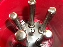
Since the (intentional or unintentional) interruption of the circuit by disconnecting the plug connection can lead to a switching arc at the pin and socket and thus to greater wear of the plug connection and possibly to a risk to the person pulling the plug, the IEC 60309 plug connections From the 63 A version, a pilot contact is optionally provided in the middle. This is shorter than the remaining contacts and is intended to interrupt the control current for systems when pulled under load or trigger a contactor in order to disconnect the circuit at a switch designed for this purpose before this happens at the plug connection. The pilot contact is there to connect the plug to the neutral conductor. This means that a contactor drive can be switched to the neutral conductor via one of the outer conductors and thus switch off the device before the plug contacts are disconnected.
Most used types
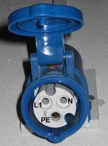
The most common types are CEE blue L + N + PE and CEE red 3L + N + PE. On the connector housings, the outer conductors are sometimes referred to as “P” for “phase” instead of the letter “L” for the English live , in German “conductor” - not to be confused with “PE” P rotective E arth , which denotes the protective conductor . The housing color refers to the regionally available mains voltage , yellow for 110 V, blue for 230 V and red for 400 V. The 16-ampere and 32-ampere versions are predominant in each case.
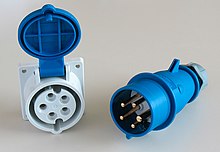
L + N + PE, 6h
The blue connector "L + N + PE, 6h" can be used for the single-phase 230 volt alternating current network common in European households . The plug is technically higher quality than the plug connections common in house installations (e.g. Schuko plug in Germany and Austria or SEV 1011 in Switzerland):
- mechanical protection of the pins
- Reverse polarity protection (compared to Schuko)
- Plug-in security through locking
- larger contact areas
- higher contact pressure
- permanently current-carrying up to 16 amps (compared to Schuko and SEV 1011 types 12 and 13)
- international standardization
- no "cheap designs" due to clear specification of the materials to be used
- Due to the IP44 degree of protection , the plug connections can also be used outdoors
- (IP 4 x = protected against solid foreign objects with a diameter ≥ 1.0 mm & protected against access with a wire)
- (IPx 4 = protection against splashing water from all sides)
Larger versions of the blue connectors up to 32 A, 63 A and 125 A can be used for higher AC currents, although these are rarely found.
Since the blue "L + N + PE-6h connectors" can be found almost universally in Europe on campsites or marinas , they are often colloquially called "camping plugs" or "caravan plugs". They have also replaced other connector systems in marinas. In addition to Switzerland, they are also used in transport, industrial, construction and commercial operations (among other things, high-quality server racks are connected via these plugs).
Mains switches in end devices often only switch single-pole. In contrast to the Schuko system, these plug-in connectors ensure that the defined contact assignment ensures that the outer conductor and not the neutral conductor is always switched. Adapter cables from a Schuko plug to a blue CEE AC coupling therefore do not conform to the standard (phase safety). With adapters from a blue CEE socket to an SEV 1011 coupling, type 23 must be used with the latter, as only this type is specified for 16 A.
In Switzerland, the CEE-16 A sockets (corresponds to SEV type 63) are only permitted in camping areas and at boat moorings, elsewhere the SEV-1011 plug type 23 is to be used. The sockets specified for 32 A are not approved in Switzerland, as a type 7 plug of the SEV-1011 standard can be plugged into the CEE socket in such a way that contact between the type 7 earth pin and the outer conductor of the CEE Socket is made.
3L + N + PE, 6h
In most European countries that use 400 V three-phase alternating current , the red connector "3L + N + PE, 6h" is preferred, mostly in the versions for 16 A and 32 A. Due to its widespread use, the five-pole plug is used in German In the linguistic area, colloquially known as “three-phase plug” (although the IEC-60309 standard also includes four-pole plugs for connecting three-phase alternating current without a neutral conductor). This plug combination is used to connect “three-phase consumers” (construction machines, heaters, motors, small machine tools and so on) to the three-phase AC network. They are also used at high currents (such as lighting and sound systems in stage technology ).
The plug connections are available in the versions 16 A , 32 A, 63 A and 125 A. The versions for 16 A and 32 A look the same at first glance, but the 32 A version is slightly larger than the 16 A version. The plug connections have five contacts, three of which are the external conductors (L1, L2, L3) of the network , one leads the neutral conductor (N) and the thicker, leading one leads the protective conductor (earth potential, PE).
L + N + PE, 4h
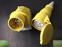
The yellow connector "L + N + PE, 4h" had spread in Great Britain in the outdoor area, before it was largely switched from 110 V to 230/240 V there. In wide - but decreasing - areas, a double voltage feed in the household sector is still common. The IEC-60309 connectors are generally called "MK Commando" after their first use in this L + N + PE design for 110 V.
3L + N + PE, 9h
The blue connector "3L + N + PE, 9h" is available in the United States as an alternative to the NEMA connectors outdoors, but is also used in other countries with 120 V (sometimes 110 V) mains voltage. The plug-in system is particularly widespread in event technology - however, three-phase power is usually not tapped here, but rather the single-phase three-wire network connections common in the USA (completely uncommon in Europe). Alternatively, 120 V can be tapped between the outer conductor and neutral conductor, or double the voltage between two outer conductors with 240 V is taken. Since no three outer conductors have to be passed through for these two operating modes, there is also a (non-standard) yellow four-pole connector for 120 and 240 V single-phase alternating current.
3L + PE, 6h
Three-phase motors do not require a neutral conductor for operation (colloquially in Germany: “ Farmer's three-phase current”), which is why, in addition to the five-pole three-phase plug , there is also a four-pole variant “3L + PE, 6h” in red for 400 volts three-phase alternating current. In practice, however, you will find old four-wire cables with five-pin plugs. For this reason, in the case of unknown cables with five-pole plugs and couplings, measurements should be carried out (for example with a continuity tester) to determine whether the neutral conductor is carried. If this is missing, consumers connected via this cable do not work for 230 V - they need the neutral conductor. If different devices are connected to different external conductors, this can lead to overvoltage and destruction of devices. Extension cord u. The like with five-pole plug connectors without an accompanying neutral conductor are not permitted. Four-pole connectors are available for this purpose. Machine connection cables are often four-core if the machine does not require a neutral conductor. This saves copper and is not a problem, as the wiring of the machine does not allow the connection of additional consumers. The protective conductor must of course also be present in this case, as well as a correct protective conductor connection to the supplying socket. Since neither is required for the function, a protective conductor test is also recommended here .
7-pole: 3L + N + PE + 2 special lines, position of the protective conductor depending on the application from 1h to 12h
7-pole plugs and sockets offer solutions for multi-functional requirements in industry, agriculture and trade. For example for the following functions:
Star-delta starting, regulating, controlling, monitoring, reporting, acknowledging, electrically locking.
Special applications
Phase reversing plug
The wiring sequence of the outer conductors (phase sequence) is prescribed with a clockwise rotating field , i.e. when looking at the socket, first the first, then the second and finally the third outer conductor must reach its voltage peak in a clockwise direction. In practice, you cannot always rely on the correct phase sequence; it is not always adhered to due to a lack of test tools such as a rotary field measuring device or for convenience. Therefore it can happen that three-phase motors do not turn in the expected direction of rotation. This can be remedied by exchanging two outer conductors in order to create a clockwise rotating field. In the case of phase inverter plugs, this can be done by turning two plug contacts, which are attached to a rotatable plate for this purpose.
Direction of rotation test plug
Several manufacturers offer test plugs to check the correct direction of rotation of three-phase sockets and coupling connections. Here the test device is already integrated in a suitable connector and glow lamps or several LEDs indicate whether the phase sequence is correct or incorrect, or whether a phase is missing.
Adapter cables
Adapter cables are often used to establish a mobile electrical connection if the desired plug connection is not available on site. Several useful variations can be found. In individual cases, adapter cables that are not permitted in accordance with the standards can also be encountered, which can represent a hazard without this being clear to the user without electrical training. Reverse polarity, which is dangerous to people, or over-protected cable cross-sections and devices that pose a risk of fire can occur.
See also
Web links
swell
- ↑ General Introduction of CEE plugs and receptacles . Rey & Lenferna. MENNEKES industrial plugs and receptacles. Retrieved on September 3, 2011: "History: CEE plugs and sockets base on the" CEE 17 "standard (also BS4343) which was introduced in the 1960s and that later led to the am IEC 60309 standard."
- ↑ BGV A3: Electrical systems and equipment (PDF; 660 kB) BG regulations / accident prevention regulations. March 1, 1979. Archived from the original on October 27, 2011. Info: The archive link was automatically inserted and has not yet been checked. Please check the original and archive link according to the instructions and then remove this notice. Retrieved on September 1, 2011: "Changeover from three-phase plug devices according to the old standard DIN 49450/49451 (flat plug device) to the circular plug device system according to DIN 49462/49463 by December 31, 1997"
- ^ Gerhard Kiefer, Herbert Schmolke: VDE series 106; "DIN VDE 0100 applied correctly, installation of low-voltage systems clearly presented" . 5th edition. VDE Verlag GmbH, Berlin and Offenbach 2012, ISBN 978-3-8007-3384-2 , p. 408 (Table 21.1) .
- ↑ http://www.toplight.ch/info/ch_plugs.pdf
- ↑ Wolfgang Burmeister, André Croissant, Matthias Kraner: The construction site manual of electrical installation . 2nd Edition. Forum Verlag Herkert, 2014, ISBN 978-3-86586-289-1 ( limited preview in Google book search).


