Hazardous area clearing system
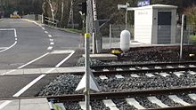
A danger area clearing system is a technical system that monitors the danger area of the crossing area of rail and road including a safety area at level crossings . It is intended to prevent a railway vehicle from colliding with an object located in the danger area or from being locked in the danger area at all. Technically this is partly induction loops via infrared - light barriers or radar implemented systems.
background
For a number of reasons, something could still be in the danger zone at the point in time at which the barriers for the passage of the train close. The more tracks are next to each other, the longer the crossing takes, especially for pedestrians . According to Section 12 (1) StVO, vehicles are prohibited from stopping at level crossings, so that, according to Section 1 StVO, driving into the danger area should be avoided even in the event of a backlog when driving with foresight. Nevertheless, careless road users often come to a stop at the level crossing in such situations.
While unrestricted level crossings and level crossings with half barriers theoretically enable the danger area to be cleared at any time, with full barriers and half barriers with full closure there is a risk that a pedestrian or a vehicle can be trapped between the barriers. For this reason, level crossings were previously monitored by a gatekeeper or the dispatcher in the signal box through direct inspection, and later also via video transmission. In the course of the modernization of older interlocking systems with mechanical or relay technology to computer-aided electronic interlockings and the associated growth in the area of responsibility of an interlocking, visual monitoring would be too complex and unprofitable. According to the Railway Construction and Operating Regulations, the waiver of visual monitoring is permitted, provided that the closing of the barriers is coordinated with road traffic by means of light signals and that technical facilities determine that the level crossing is free.
If the barriers are now to be closed for a train to pass through, the traffic lights and the entry barriers for road users in front of the level crossing first ensure that no road users can enter the danger area. At the same time, the sensors check the danger area. If this is free, the remaining exit barriers can be closed for full closure after the clearance time. If there is still something in the danger area, the closing process can be stopped or, if necessary, the barriers can be opened again. Only when the danger area is free with the barriers closed and a monitoring delay time has expired can the cover signal in front of the level crossing be set to move. Otherwise, or if an object subsequently enters the danger area, the dispatcher is notified electronically. However, the latter is not provided for in the current systems in Germany. If the train has already passed the signal at this point in time, it can only be stopped by means of an emergency stop order.
Sensor types
Induction loop
In 1999, which was commissioned by NS Railinfrabeheer of Pintsch Bamag from the developed for Germany Series RBÜT a plant ADOB derived which can warn the driver before a blocked danger zone using additional signal. In addition to radar sensors, this also happens through induction loops in the roadway.
Infrared light barrier
The infrared light barrier only works properly if it is aligned diagonally from the left St. Andrew's cross on one side of the level crossing to the right St. Andrew's cross on the other side of the level crossing (the other light barrier monitors the second diagonal). Another light barrier must also control the barrier or signal light for road traffic.
Radar sensor systems

At level crossings that are not directly visible through an interlocking, video surveillance is increasingly being replaced by a radar sensor reporting system. A radar mirror rotating horizontally at 1 Hz is located in the housing of the scanner. The hazardous area is scanned in 1 ° steps. A distance measurement to the next object is carried out in each of the steps. During the setup, the device is programmed with the start and end of the hazardous area for each of the measurement angles. If an object is within the limits, occupancy is reported to the level crossing control. In addition, there are at least three cube-corner mirrors at the level crossing that reflect the radar signal directly, one at the beginning, one roughly in the middle and one at the end of the angular range to be monitored. These prismatic mirrors are used for self-tests. The distances and angles of the prismatic mirrors are programmed into the device when it is set up. If the triple mirror is not detected, the device also reports an occupancy. In this way, the danger area for the scanner can be spatially limited and correct functioning ensured. Measurements are only taken in an area from about 50 cm to about 1 meter above the track.
Web links
- Locations of level crossings with hazard area clearance detection systems on OpenStreetMap (incomplete)
- Illustration: "Am Wasserturm" level crossing on the Coesfeld - Dorsten line
- Optimal integration of RBÜT and GFR ( Memento from March 4, 2016 in the Internet Archive ) (PDF; 103 kB)
Individual evidence
- ↑ Use of the RBÜT at NS Railinfrabeheer (PDF), article from the specialist journal SIGNAL + DRAHT (92) 7 + 8/2000
- ↑ Honeywell Radar Scanner, Advantages & Benefits. (PDF; 347.73 KB) Honeywell Regelsysteme GmbH, August 8, 2012, archived from the original on October 1, 2015 ; accessed on September 1, 2013 .
