
Level crossing (Germany)

.jpg)
A level crossing , formerly way (e) crossing , is a level crossing of railway tracks according to § 11 Railway Construction and Operating Regulations (EBO), as well as a crossing of a special or according to § 20 of the Tram Construction and Operating Regulations (BOStrab) independent track body with streets, paths and squares. Crossings to systems according to EBO, which are only used for internal traffic, and crossings for travelers are not considered level crossings.
In Germany around 2008 there were around 45,000 level crossings in the railway sector , of which around 20,400 were operated by Deutsche Bahn AG . In its 2019 Infrastructure Status and Development Report, Deutsche Bahn puts the number of level crossings in the DB network (including DB RegioNetz Infrastruktur GmbH (RNI) ) at 13,626, with a downward trend.
History of the designations
Historically, the term level crossing had a completely different meaning than it has today. It was used publicly for the first time in 1849 in the first association regulations of the Association of German Railway Administrations, which came into force in 1850, for the transfer of goods wagons from one railway administration to another. Literally it says in § 2:
“In accordance with § 1 of the regulations, it was agreed that the reloading of goods should be avoided when transferring from one railway to another, as long as the passage of the same in the same wagons can contribute to their conservation or faster transport. The administrations will therefore mutually allow foreign wagons to be transferred to their railways and their wagons to other railways ... "
Cauer also uses a level crossing as the transition of wagons or trains from one regional railway to another when operating joint stations of two regional railroad administrations . With further nationalization and further and numerous international regulations on wagon transfers, personnel transfers, etc., the term in this sense finally fell into disuse in the 1920s.
For the level crossing of streets and paths with a railway line, different names were used for the regional railways, such as crossroads , plan crossing , crossing and level crossing . The term way crossing used by the Prussian State Railways has prevailed , which is included in the operating regulations for the main railways in Germany of July 5, 1892 (Section 4, Paragraph 6) and in the railway regulations for Germany's secondary railways of July 5, 1892 (Section 21, Paragraph 2 and 4) and was adopted in the Railway Building and Operating Regulations (BO) from 1904 that replaced them. By Victor of Röll in his Encyclopedia of railways in 1912 proposed unification to railway crossing was not included in the law and practice.

|

|
|
|
Reichsgesetzblatt, 1910, item 5, page 397
|
Reichsgesetzblatt 1934, Part I, p. 864, see Paragraph II. (2)
|
With the increase in motorized road traffic and the associated adoption of regulations for road traffic, a new development of the term arose. On the basis of the law on traffic with motor vehicles of May 3, 1909, the Federal Council of the German Reich issued the regulation on traffic with motor vehicles on February 3, 1910 . In § 18 it was determined: "... when approaching railroad crossings at rail level ... you must drive slowly and carefully so that the vehicle can be brought to a stop immediately."
From the further development of the term, the adoption of this designation in the Reich Road Traffic Regulations of September 29, 1934 is central after 1920 . On September 24 of the following year, the regulation on the marking of railway crossings was issued based on this. From this point in time at the latest, a different view of the level crossing developed from the history of the technical safety devices , so that the term (since the historical one had meanwhile been forgotten) was finally used in road traffic law for the intersection of roads and roads with railways.
Nonetheless, even the last edition of the BO in 1943, before the end of the Second World War, adhered to the concept of road crossing from the perspective of the railway.
After 1945 it became apparent in the terminology of the railway sector that an analogue had to be created for the words railway overpass and railway underpass : For this purpose, the term railway crossing , which has meanwhile been established by road traffic law, has now been adopted, or level crossing for short . In this form it was included in the Federal Republic of Germany on May 28, 1967, in the fundamentally revised and now Railway Construction and Operating Regulations (EBO). At the Deutsche Reichsbahn in the GDR, the BO in the version from July 23, 1943 until German reunification remained in force, so it remained here with the original name Wegübergang until 1990 .
In the ordinance on the construction and operation of trams (tram construction and operating regulations, BOStrab) of August 31, 1965, a completely revised set of rules was created in the Federal Republic of Germany compared to the BO Strab of 1938. Here, the term level crossing is used for the first time for the road crossings previously known as this (Section 20 BOStrab 1965).
In the similar complete revision of the ordinance on the construction and operation of trams (Tram Construction and Operating Regulations , BO Strab) of March 25, 1969 in the GDR, which replaced the BO Strab from 1959, the designation level crossing is also introduced. However, since the BO of 1943 was applicable in the railway sector, the formulation crossing with other traffic routes was selected in Section 20 and the designation level crossing was introduced via the detour of the road traffic regulations (from 1964) as well as in Annex 2.
Legal basis
railroad
Basic regulations on level crossings can be found in the Railway Building and Operating Regulations (EBO). In addition to basic definitions, the EBO contains information on types of security and permissible speeds.
The Railway Crossing Act (EKrG) stipulates, among other things, that no new level crossings may be built; However, exceptions are permitted. Existing systems should be replaced by height-free overpasses if possible (or closed without replacement). In addition, the EKrG provides information on the cost sharing between the building contractors for the construction and maintenance of level crossings.
These fundamental laws and ordinances are specified by directives in the area of Deutsche Bahn AG (and other railway infrastructure operators to which the operational regulations of Deutsche Bahn AG also apply). For the operational staff of the railway companies, the guideline 408 driving regulations and guideline 301 signal book are particularly relevant. For road users, behavior is regulated in the road traffic regulations.
tram
.jpg)
Regulations in connection with tram and underground underground lines can be found in Section 20 of the Tram Construction and Operating Regulations . Many tram systems are more and more similar to the railroad, which led to the BOStrab being amended in 2016. In the course of this, § 20 was adapted to the requirements of modern tram infrastructure and takes the increasing individual traffic into account.
While a level crossing was previously only allowed to be designated as such if there are St. Andrew's crosses there, a distinction is now made according to the alignment. All level crossings of special and independent railway bodies with streets, paths and squares count as level crossings, regardless of whether a St. Andrew's cross is attached. The priority in turn results from the StVO. It should be noted that in § 19 of the StVO the priority relates to the presence of a St. Andrew's cross, while the associated administrative regulation states that the installation of special track structures that are in the traffic area of a street can be omitted if the vehicle drivers turning or crossing are clearly visible can recognize that rail traffic belongs to traffic on the road with right of way.
Since trams take part in road traffic on a track that is flush with the street, their intersections with streets, paths and squares do not count as level crossings unless there is a St. Andrew's cross there.
The security of the level crossings is also divided into the different routes. While the technical security can be dispensed with in the case of road-flush and special railway bodies and general security is guaranteed via “sight”, there is a gradation according to the volume of traffic and the speed of the crossing road with independent railway bodies. Technical safety is required at level crossings on sections of the route on which tram trains with train protection operate or which are used by more than 100 vehicles per day or at a speed of more than 50 km / h on the crossing road.
Tram trains do not take part in road traffic on special and independent tracks with technically secured level crossings.
Technical security
Level crossings are not permitted on railway lines in Germany with a maximum speed of more than 160 km / h. Due to the lower static friction and the larger moving mass, a rail vehicle requires a significantly longer braking distance than a road vehicle. This means that rail traffic at the level crossing has priority over road traffic. This priority, which is legally documented in Section 11 (3) of the Railway Building and Operating Regulations (EBO), is displayed on both sides of the level crossing with the St Andrew's cross (StVO sign 201). Road users must stop in front of the St. Andrew's Cross when the level crossing is secured. The railway construction and operating regulations do not require the installation of St. Andrew's crosses for field and forest paths , footpaths and private paths . This also applies to roads and paths over sidings if the level crossing is secured by guards for the use of rail vehicles (see below). Emergency vehicles must also stop in front of level crossings if this is required for other road users.
For the traffic light systems at technically secured level crossings, the guideline for traffic light systems is decisive, which also regulates that separate barrier drives - if necessary together with the pedestrians - are to be set up for structural bike paths. Light signals are required for road traffic, which must first be given in the yellow-red sequence from the off position. Level crossings on single-track routes with little traffic significance can only be equipped as traffic lights or stop light systems with road signals without barrier drives. Likewise, on the basis of RiLSA, so-called crossing aids for the visually impaired can be built in, with pushbuttons on light signal poles and the acoustically intelligently attached loudspeakers at the level crossing acoustically indicating the clearance of a level crossing for the visually impaired to cross vibrate when the level crossing is cleared.
safety

The number of accidents at level crossings has been falling in Germany for decades. In 2016 there were 140 accidents at German level crossings. In 2008 there were 207 accidents, including 52 fatalities, in 2003 there were 258 accidents and in 1996 there were 563 accidents. In 1993 there were 782 accidents at level crossings.
The worst accident at a level crossing in Germany was the railway accident in Langenweddingen on July 6, 1967. Due to a malfunction and a subsequent operating error at the barrier system there, a passenger train collided with a tanker truck. 94 people were killed.
Around 500 million euros are invested annually in removing level crossings and improving safety technology.
Security types

Level crossings must either be secured with technical equipment or other measures . There are no “unsecured” level crossings, even if this word is often used, mostly in reports of accidents at level crossings. Correct is not technically secured . Which type of security must or may be used depends on the strength of the road traffic and the type of railway line , whether main or branch line , single or multi-track line, footpath , cycle path , forest path or private path.
The volume of road traffic is measured according to the number of motor vehicles that cross a level crossing alongside other traffic within one day. Level crossings have hereafter
- light traffic with up to 100 vehicles,
- moderate traffic with 100 to 2500 motor vehicles or
- heavy traffic with more than 2500 vehicles per day.
For level crossings with heavy traffic, the German railway building and operating regulations stipulate technical safety
- Light signals or
- Flashing lights or
- Light signals with half barriers or
- Flashing lights with half barriers or
- Light signals with barriers or
- Barriers.
This applies equally to main and branch lines .
Light sign

|

|
|
|
Example and animation of light signals
|
||
The traffic light-like light signals were first ordered from May 9, 1991 when the third ordinance amending the railway construction and operating regulations of May 8, 1991 came into force . Since then, they have been intended to replace the older flashing lights on routes with little traffic, but also to be used at barriers.
With light signals one's traffic signal system (commonly known as "light" or "needs light" called) meant that only shows a yellow and a red phase. The green phase that is otherwise common with a traffic signal system does not exist here. In the course of securing the level crossing in Germany, a yellow and after 3–5 seconds (yellow time) a red continuous light is lit. At the end of the security phase, the red light goes out immediately without a yellow phase, and any barriers installed open.
If a level crossing is in the immediate vicinity of an intersection or junction, there is a risk of backwater in the danger area of the level crossing. This is countered in two ways: If the intersection / junction is equipped with a light signal system (LSA), the level crossing safety system (BÜSA) is technically connected to this and the signaling of the LSA is coordinated with the level crossing safety. One then speaks of a BÜSTRA system.
If there is an intersection or junction immediately in front of the crossing that is not equipped with a traffic light system, there is also a risk of backlogging into the danger area of the level crossing due to the turning relationships. To counter this danger, upstream traffic lights are set up in front of the level crossing. These upstream light signals do not have a St. Andrew's cross and begin to block the access to the level crossing before the actual light signals (pre-lighting time) and enable road traffic giving right of way to clear the danger area of the level crossing or no longer to reach it. As a rule, the red lights at the upstream traffic lights go out when the barrier booms reach the blocked position.
Warning lights, flashing lights and stop lights

|

|
|
|
Example flashing light / stop light and flashing light animation
|
||
Flashing lights , also known as flashing light systems (abbreviations: Blifü (flashing light system with remote monitoring) or Blilo (flashing light system monitored by the train driver, i.e. with monitoring signals ) or in the area of the Deutsche Reichsbahn stop light systems, show a red flashing light when a train approaches in Germany. Flashing plants flashing on both sides of the street usually alternates with the street, as opposed to the older maintenance lighting systems are flashing on both sides of the street in sync . Alternating flashing was introduced here in the 1970s with the type Hs 64 automatic for lines with an automatic line block and in 1987 it became a standard design. If a level crossing is confusing or in the curve area and therefore the flashing lights can only be seen late, it can be equipped with an additional flashing light above the road.
It is assumed that the red flashing light is sometimes misunderstood as a warning light and not viewed as a stop signal (see also section Behavior at level crossings ), which is why flashing lights are no longer installed as a safety device to be newly installed or in the case of major renovations. It is permissible to move the flashing lanterns from the center of the warning cross to a signal screen above it. According to the unification agreement, the operating permit for the Reichsbahn systems was limited to 31 December 2010. They were to be converted - at least the flashing light must be removed from the warning cross and moved. A few stop light systems will still be available and in operation in 2020.
Development and introduction of the warning light systems
As early as 1925, experiments were carried out with electrically controlled level crossings in the German Reich , but it took another decade before the systems were fully developed. The aim was to replace the personnel-intensive guard-operated mechanical barrier systems. In October 1929 the Deutsche Reichsbahn gave the first approval for the construction of two different test systems on branch lines. The first was built by the ADAC on the Königs Wusterhausen – Beeskow line, the second near Friedersdorf was built by the United Railway Signal Works. Both warning light systems had a lantern fed with acetylene , in which the color change from white to red was achieved by an electrically controlled shutter. By decree of the Reich and Prussian Ministry of Transport of December 30, 1935, the warning light systems were recognized and generally approved as equivalent to the barrier. Several models of warning lights were used to secure the unrestricted level crossings.
Innovations at the Deutsche Bundesbahn

|

|
|
|
Warning cross with flashing light from 1953
|
St. Andrew's cross with flashing light and half barrier. Introduced in 1961 with this combination and this ideal appearance
|
While the previous, very reliable warning light systems in West Germany showed a white, slowly flashing optics when the crossing was free and a red, rapidly flashing light when a train was approaching, the German Federal Railroad experimented at the beginning of the 1950s with experimentally put into operation Systems that only had a red flashing light. The basis for this development was the efforts of the Union International des Chemin de Fer (UIC) from 1950 to standardize this type of security system across states. With the approval of the Federal Ministry of Transport, a large number of the new flashing light systems were installed as early as 1953.
In the Federal Republic of Germany, by decree of the Federal Minister of Transport on January 1, 1961, the name warning light changed to blinking light and the warning cross became the St. Andrew's cross . With the ordinance at that time amending the Railway Construction and Operating Regulations (BO) of December 20, 1960, the construction of the previous flashing lights and signal screens also changed. The older flashing light systems, including pre-war versions, were only allowed to remain in use until December 31, 1963. The signal lanterns have also matured over the years. At the beginning, the lanterns had light exit openings with a diameter of 18 centimeters. With the introduction of the EBÜT80 technology ( standard level crossing technology ) optics from Scheidt & Bachmann , which had a larger diffuser, were also used. In the meantime, a switch has been made to the use of signal heads with a diameter of 210 and 300 millimeters known from traffic light construction. In general, however, many different companies were involved in the construction of the flashing lights over the years, so that different construction methods can be found today.

|

|
|
|
Illuminated display "2 trains" and rattle alarm clock (below) / animation
|
||
With the change in the railway building and operating regulations in West Germany from January 1, 1961, at little-used multi-track level crossings, which should generally be three to four meters wide, instead of half-barriers, signal screens with a red flashing light and the yellow one below it Illuminated "2 trains" and an alarm clock were erected. The red signal lights, which flashed sixty times a minute, were switched on by an arriving train by driving on a rail contact (switch-on point); it went out when the last axis left the switch-off point at the level crossing. The duration of the flashing time from switching on the system to the arrival of the train at the level crossing depended on the local conditions and the speed of the individual train. If a second train passed the switch-on point on the second track before the first train had completely passed the level crossing, the red flashing light continued to illuminate. At the same time, a yellow neon "2 trains" appeared under the flashing light and a loud rattle alarm went off. The bell of this alarm clock only sounded in connection with the appearance of the neon sign. The road user was made aware of the neon sign and the alarm clock that the crossing was still blocked for a second train after a train had passed. All important switching elements of the system were available twice. If a subsystem failed, it went unnoticed by the road user. In addition to this innovation, the lightning arrow was introduced on the St. Andrew's cross with the newly ordered sign, which indicated an electrically operated route. At the beginning of 2020, seven such systems were still in operation, three are to be dismantled in the course of the year.
Developments at the Deutsche Reichsbahn
In the German Democratic Republic, the designation Haltlicht was introduced instead of the previous warning light , while the designation warning cross remained. In terms of development, the Deutsche Reichsbahn took a slightly different path than the Bundesbahn. The development work on special street signal lamps with Fresnel stepped lenses was discontinued for cost reasons and modified main light signal lamps with aspherical lenses were used. For the road signals, because of the DC voltage supply, housings with a flat cover without a transformer, a lighter colored disc (so-called WÜ red ), a 48 ° diffuser with a different depth scattering sector (the height of the light point is significantly lower than with railway signals) and otherwise unusual double-filament signal lamps are used with 20 volts and twice 10 watts. As a rule, both filaments are in operation, the upper secondary filament is set to a lamp current that is 20 milliamperes lower so that it does not fail at the same time as the main filament.
In the GDR, stop lights were only permitted on single-track routes. The flashing light remains active until the level crossing safety system is switched off. In the case of the systems of the former Federal Railroad, this happens approximately at the same time as the barrier drives start up, whereas in the case of systems built by the Reichsbahn, this happens only when the barrier booms have reached the open, i.e. are fully open. The cause is the different behavior when it is switched on again, for example because of a journey on the neighboring track. In the case of Reichsbahn systems, the drives immediately revert to the locked position if they are switched on again during opening ( reverse ). Federal railways and systems built later open completely and only switch on again for road users after ten seconds ( minimum green time ). However, this time must be taken into account for the approach routes. Systems with a minimum green time therefore require longer blocking times.
Barriers
Barriers serve as a direct barrier. Its introduction goes back to Max Maria von Weber , an engineer and railway pioneer of the 19th century. Depending on the width of the road, two or four barrier booms are used, which are open in the basic position and are lowered across the road or along the path. They usually consist of red and white striped material (steel, aluminum, glass fiber reinforced plastic , previously also wood) or are covered with a striped retroreflective layer. The use of barrier booms without these security coatings / stickers is not permitted on public land in Germany. Some barriers are equipped with a curtain made of chains, grids or the like, which is intended to prevent the barrier trees from being undermined or driven under. In the case of four-way barriers, the access side to the level crossing is blocked first. In addition to the road barriers, separate pedestrian and cycle path barriers can be installed. In order to make the barrier booms more easily recognizable for road users, in the case of electric barrier drives built around 1992, they are no longer vertical as they used to be, but are slightly inclined to the road at 83 to 87 °. This is intended to make them more eye-catching and thus increase awareness when approaching a level crossing. Three-way barriers are rare, they are necessary when the width of the street in the crossing area changes, for example due to the location at an intersection.
There are two types of construction: full barriers and half barriers .
There were particularly secured level crossings in the area of the inner-German border , where the column path of the blocking system crossed railway lines in the death strip. Such a crossing existed at Berlin-Staaken train station . After the Berlin Wall opened, it was opened to general traffic and called the "Elephant Gate". Instead of a barrier, it was equipped with barred sliding gates to prevent unauthorized entry of the railway system located in the border area and open towards West Berlin .

A transit train from Hamburg passes through the border systems at Berlin-Staaken station , in front of the train the level crossing for the GDR border troops, 1986

Formerly located in the death strip "Elefantentor" level crossing in Berlin-Staaken , 1991

"Elefantentor" on the former Kolonnenweg when open


Full barriers

Full barriers block the level crossing in the lowered state across the full width of the street or cause a full closure. In order to ensure that no vehicle is locked in, optical monitoring of the danger area is required for full barriers. This can be done locally by a gatekeeper, a dispatcher in the local signal box or remotely monitored by monitors. A rail vehicle may only be allowed to travel after it has been determined that the person is free. Within train stations, this often takes place in conjunction with the setting and dissolution of routes . Gatekeepers who operate the barriers with the barrier winch are no longer used that often, but this type of operation still serves as a substitute measure in the event of a fault in a barrier system. Electric barriers are driven either hydraulically or with electric motors, which either move the barrier boom directly via a gearbox or, less often, via a barrier winch and wire pull cables ( Dresden barrier ). The barrier boom is held in the balance by a counterweight or a spring balancer - if possible with tilting behavior, so that it remains in both end positions when suspended. In the case of newer electric barrier drives, the boom is held in the open position by a closed-circuit operated holding magnet. In this case, the barrier boom is overweight, so that in the event of a malfunction it automatically enters the locked position even without motor current (so-called emergency or replacement closing).
The so-called full closure can also be achieved with shorter barrier booms by installing a barrier frame on each side of the street (four-way barrier) . The barrier drives in the direction of travel behind the crossing then close with a time delay to ensure that the level crossing is cleared. These barriers in particular are then equipped with underflow protection. If a full closure is achieved, one usually speaks of full barriers, since the crucial difference is the possibility of locking in road vehicles, regardless of how this is locked (with two or four barriers). The optical monitoring of full barrier systems can also be replaced by hazard area detection systems . These radar scanners have been approved by the Federal Railway Authority as a replacement for optical monitoring for some time.
Half barriers

Half barriers usually only block the access to the level crossing and thus enable the danger area to be cleared (exited) at any time, so that nobody can be trapped between the barrier booms.
Today, half barriers are mostly operated automatically by the rail vehicle via rail contacts (Fü and Lo systems) or remote-controlled from the interlocking (Hp systems). Optical monitoring of these systems is not necessary because a vehicle cannot be locked between the barriers. However, this cost advantage of the optical monitoring that is not required also has the disadvantage that road users can bypass half barriers. This is considered to be a dangerous interference with rail traffic. Broken down or crashed vehicles may not be discovered in time. That is why there is an increasing number of danger zone detection systems being used here.
Half-barriers and, in this case, the technically identical stop light systems of the DR types always have remote monitoring and driver signaling, either by monitoring signals or by means of covering by suitable main signals.
Call barriers
So-called call barriers are often used on subordinate routes , which are closed in the basic position and are only opened by the gatekeeper "on call". According to § 11 (17) Railway Building and Operating Regulations (EBO), they must be equipped with an intercom if they cannot be seen from the control point. Barrier movements must be announced by the operator before they are executed. Alternatively, a hazard area clearance system can be installed to check that the level crossing is free if the feedback is forgotten. Call barrier systems are in principle full barriers.
Audible warning

|

|
|
|
Alarm clock at a street signal in the former DB (left) and DR network (right)
|
||

In Germany, as in other countries, level crossings usually have an acoustic warning device in addition to the installed technical security. Often it is a chime that announces the imminent closing of the barriers with a number of chimes depending on the local conditions. In the case of locally operated mechanical barriers, this lead-in path is occasionally missing . Older electrical systems as well as mechanical systems supplemented by road signals are usually equipped with bells - called alarm clocks in technical terms. To avoid noise pollution for the residents, many rattle alarms at WSSB systems were switched to impact operation. Flashing light systems - with the exception of those with an additional display of 2 trains - generally only had alarm clocks with a single strike. Systems with light signals and alarm clocks (mostly younger Lo 57-Lz or older EBÜT systems) are less common, they also emit an intermittent tone.
Newer systems with light signals occasionally have a loudspeaker system that plays an electrically synthesized bell tone. They are used more often in new systems with pedestrian traffic. The sound can be adjusted in the modules of some manufacturers, but is largely uniform in Germany. In a few older systems there is a two-tone sound, with RBÜT / RBUEP systems from the manufacturer Pintsch Bamag a slightly lower tone is emitted. In very rare cases, for example at the Schiffahrter Damm level crossing in Münster , an automatic warning is played, here: “Please leave the level crossing! The barrier closes! ". Flashing light systems can also be retrofitted with such an acoustic module.
In the case of stop light systems, the acoustic warning ends when the switch-off point is entered, in the case of flashing light systems when the system is switched off after the train journey, and in the case of full and half barriers, as a rule, when the barrier booms are in the blocked position.
Sound samples:
Other warning signs
Additional information on technical safety devices or on the St. Andrew's cross should further improve safety:
- in Germany shows a lightning symbol in the middle of the St. Andrew's Cross that the railway line, an electric overhead line has
- An additional sign with a black directional arrow under the St. Andrew's cross indicates that it only applies to road traffic in the direction of travel shown
- When entering port or industrial areas in Germany, an additional sign with the words “Port area, rail vehicles have priority” or “Industrial area, rail vehicles have priority” may be attached.
Non-technically secured level crossings

No technical safety is required for level crossings on main lines that run over secondary tracks and for level crossings on secondary lines if there is light or moderate traffic on the road. These level crossings are secured by the St. Andrew's cross (sign 201). Instead of technical security, there is the
- Overview of the railway line or in combination with the following measures
- audible signals from the railway vehicles (horn), possibly in connection with a
- Reduction of the speed of the railway vehicles at the level crossing or the
- Securing through posts (employees of the railway).
The overview of the railway line alone is sufficient at level crossings with low traffic. The overview is available when all road users can safely cross the level crossing or come to a stop in front of it. The area that has to be kept clear is called a viewing triangle or viewing area . The point where the train must be seen as a viewing point.

If there is no adequate overview of the railway line, it can be replaced by audible signals from the railway vehicles (bells and / or whistles) if the railway vehicles pass the level crossing at a maximum of 20 km / h and on field and forest paths with a maximum of 60 km / h . The driver is shown at which points they must be given with whistle boards , signal Bü 4 (or Pf 1 or Pf 2 ex- DR ), or bell (signal Bü 5). Signal boards are at the viewing point. The possibly necessary reduction of the speed with the slow speed signals (old Lf 4 and Lf 5 ) now Lf 6 and Lf 7 are displayed. The black whistle board Bü 4 only exists in the area of the DB today, it was only intended for main lines.
At level crossings with moderate traffic, it is sufficient to have an overview of the railway line in conjunction with audible signals from the railway vehicles. With the approval of the supervisory authority, if there is no overview of the railway line, the audible signals from the railroad vehicles are sufficient if the railroad vehicles pass the level crossing at a maximum of 20 km / h or 60 km / h.

|

|
|
|
Post security at a level crossing of a museum railway
|
... and the "Vulkanexpress" in Niederzissen
|
In the event of a malfunction, such as the failure of a technical security device, security by means of items replaces any other type of security. This type of security is often used in port , industrial and commercial areas . The guards then often secure the level crossing with signal flags or a red lamp.
Circulation barriers, rotating grilles , turnstiles or similar devices are sufficient on footpaths and cycle paths . You must interrupt the crossing footpath or cycle path in such a way that the track cannot be easily crossed, but should allow bicycles with trailers to pass through if the route is clear.
Private level crossings
A special feature are the so-called private level crossings (PBÜ): These are crossings that farmers can use to cross, especially during harvest time. In order to ensure the necessary insight into the rail traffic, special regulations for the care of the local vegetation apply on these unrestricted crossings. These measures are usually carried out by route maintenance officers . Private level crossings must meet the minimum requirements, otherwise they will be closed immediately. Examples of this are visibility due to trees, etc.
If these crossings are equipped with a St. Andrew's cross, an additional sign with the inscription “Private road - only for authorized persons!” Is attached.
History of technical safety devices

In the early days of the railroad, the technical safety devices at level crossings on the open line were always used locally. It was still exclusively a matter of barrier systems: sliding barriers near a post were moved by hand by the railway attendant, barriers on the route were opened with a wire pull and closed by slackening the wire and by the weight of the barrier; in addition, the chimes of the bell announced the imminent closing of the barrier. The operation was cumbersome and always had to be carried out outdoors. In order to improve working conditions and to reduce the workload, mechanically driven barriers were soon developed, which could be operated either with a hand crank at the level crossing itself or with a cable winch from a closed room. The drive force for closing and opening the barriers was transmitted from the cable winch by means of wire cables over a distance of up to 100 meters and more. Each of the German regional railway administrations and many signal construction companies used or supplied their own, incompatible designs. This diversity was replaced in the 1930s by the standard design that is still widespread today . The electric drive was added later. Nevertheless, the distance between the control point and the level crossing could not be extended at will, because the gatekeeper had to be able to see the level crossing even when visibility was poor in order to avoid road users being trapped between the barrier trees.
The next step was to develop warning lights that the train switched on and off. By means of monitoring signals on the route , the driver was able to monitor the function of the warning light system when the train approached the level crossing, so that the gatekeeper was unnecessary at many level crossings . By decree of the Reich and Prussian Transport Ministry on December 30, 1935, the new systems were recognized as equivalent to the barrier. Several warning light system models were used to secure the unrestricted level crossings. After initial experience, especially in the winter months, in the late 1930s the switch was made to arrange the signal screens with two warning lights only lying down. It had been shown, among other things, that snow could pile up on the barges above the optics below and thus cover the warning light above.
- Warning crosses with warning light before 1945

Warning cross with white warning light for unrestricted single-track level crossing

Warning cross with red warning light for unrestricted single-track level crossing

Warning cross with double warning light for unrestricted single-track level crossing

Warning cross with double warning light for unrestricted multi-track level crossing

Warning cross with red warning light, alarm clock and light signal Two trains for unrestricted multi-track level crossing

Newer version of the warning signal screen for unrestricted single-track level crossing


The gatekeeper initially only used the route timetable as a guide when it came to when he had to close the barriers. Later the “barrier post” was included in the line telephone connection, which connects the dispatcher interlockings at the two neighboring stations. The respective dispatcher announced the departure of a train in the neighboring station via a bell that still exists outside of Germany . The dispatcher "rang the bell" - with a certain number of chimes for one direction and the same number of chimes for the other direction. Incidentally, the gatekeeper had to expect a train at any time and constantly watch the route. The ringing signals were replaced in western Germany at the end of the 1950s by listening to the train reports that were now given by telephone over the telephone line , which until then had been carried out by telegraph using the symbols of the Morse code .
- Federal Republic of Germany from 1953

Warning cross for restricted single or multi-track level crossing (deleted in 1963 without replacement)

Warning cross for unrestricted single-track level crossing

Warning cross for unrestricted single-track level crossing

Warning cross for unrestricted multi-track level crossing (deleted in 1963 without replacement)
Warning cross for unrestricted multi-track level crossing (deleted in 1963 without replacement)


- German Democratic Republic from 1956

Gated level crossing

Unrestricted level crossing (single track)

Unrestricted level crossing (single track with stop lights)

Unrestricted level crossing (multi-track)


After the train accident in Langenweddingen in 1967, the barrier operation was changed at the Deutsche Reichsbahn. Since then, guard-operated track barriers have been closed after the train report signal, but before the train report was received, which the gatekeeper on the train report line confirmed ("Post 14, barrier closed"). Barriers in train stations were closed before a journey was permitted, and most of them were included in the route safety system. Because this dependency can be removed in the event of a malfunction, so that trains do not have to run unnecessarily without main signal operation, the term “barrier signal dependency” is used instead of “signal dependency” .
The operation of the barriers at the level crossings within the train stations or in the area of other locally manned operating points turned out to be a bit easier, because here you could transfer the activity of the barrier keeper to the already present dispatcher, point keeper or block keeper of an interlocking .
In principle, this situation did not change much into the 1960s and for a while after that. Only the technology of the relay interlocking opened up new possibilities. Electrically powered barrier systems can be integrated into the route safety system - especially if the level crossing is within a route . Today, the safety devices of such level crossings are mainly set up in the control area of the signal boxes, depending on signals. The signal with which a train or shunting run is permitted across the level crossing can only be brought into the driving position when the level crossing is technically secured. Level crossings that are not included in the route safety system today mostly work automatically and train-controlled. Here a monitoring signal or the dispatcher in the signal box ensures that the security is monitored.
As a result of increasing road traffic, with the introduction of the Railway Construction and Operating Regulations (EBO) in May 1967, the regulations on level crossings (Section 11) were extensively changed and tightened. Among other things, the option to make barriers visible to the operator only indirectly (e.g. with image transmission) has been introduced. With the Third EBO Amendment Ordinance of May 1991, the regulations for level crossings were completely revised in the light of new safety technology and new regulations for road traffic. This made it possible, among other things, to be able to do without an indirect or direct view of level crossings with barriers if there are light signals and the freedom is monitored by technical devices.
In the case of barrier systems with full barriers, despite the latest technology, the problem of monitoring the so-called "danger area" between the barrier booms has remained unchanged. For a long time, new methods, such as surveillance by radar devices, did not get beyond the experimental stage. So it was still the job of the gatekeeper to determine whether the danger area was clear with a direct view or with the help of video cameras on monitors and only then to release the signal for a rail vehicle to cross the level crossing. In the meantime, the automatic hazard area detection system is state-of-the-art using radar technology. At present, level crossings with full barriers are being converted accordingly to save costs.
Functionality and operation

|

|
|
|
Barrier winch (standard design) and associated barrier booms
|
||
A distinction is made with regard to the function and operation of technical safety devices at level crossings
- attendant
- train operated and
- signal-controlled
Plant types.
Attendant-operated systems
Guard-operated systems are always operated by a gatekeeper , who can also be the operator of a signal box. We always mean systems with full barriers, because half barriers do not constitute an independent safety device; they are only ever used in conjunction with a traffic light or flashing light system. There is only one such facility in Switzerland.
Another special feature are manual full barrier systems without barrier posts. Here the engine driver has to stop the train before crossing the level crossing. The barrier system is then operated by the train driver or the shunting personnel. This can be done, for example, by a mechanism with a hand crank. Only now is the train or the shunting unit allowed to cross the crossing. He stops again behind him, the barrier is activated again to open the passage for road traffic.
Train operated systems


Traffic lights and flashing light systems on the free route with or without half barriers can be train-operated systems . They are switched on by the train via switch-on contacts, wheel or vehicle sensors ( induction loops ) in the track or by interlocking criteria that are also used (driving on track circuits or axle counters ) and switched off via switch-off contacts, wheel or vehicle sensors on the crossing. If trains stopping at switch-on or switch-off points must be expected, track switching means, i.e. track circuits or vehicle sensors, are required. The switch-on points are marked with signal boards ( Bü 2 and Bü 3 ).
A distinction is made between train-controlled facilities in Germany
- Lo systems = engine driver monitored and
- Fü systems = remotely monitored
Investments. Which of these two types of monitoring is used depends on the type of railway, the number of tracks and the speed of the trains. Lo systems are generally only available on single-track routes if the trains pass the level crossing at a maximum of 100 km / h, in exceptional cases up to 120 km / h. There are only Fü systems on routes with higher speeds.
Switching off is similar for all train-operated systems. Depending on the design, there are one or more rail contacts directly at the level crossing. If the train crosses these with the first axle, a relay with a drop-out delay of about 6 seconds picks up. As a result, the white light on the monitoring signal is first deleted. These relays receive voltage again with each axis pulse. If the last axis leaves the off-switch, the relays drop out again after the drop-out delay has elapsed, then the barrier booms open, if present, and the system switches off. If a train stops on the crossing or moves too slowly so that two of its axles pass the contacts after the delay time has expired, this cannot be detected and the system opens by mistake. In the case of two- and multi-track systems, the track switching is available separately for each track. The system only switches off when all tracks have switched off.
In ex-DR systems, the switch-off point consists of two rail contacts connected in series or, if trains stopping, a rail contact in connection with a special track circuit or a vehicle sensor. In the case of systems with a track circuit ( linear switch-off criterion ), deactivation requires driving on this track circuit, making the rail contact effective and clearing the track circuit. With flashing light systems in the old federal states there is only one single contact at the transition with Lo systems and with Fü systems two redundant contacts mounted opposite on the track. Many of these systems, especially those that are remotely monitored, were therefore later retrofitted with vehicle sensors.

Alternatively, with newer systems or additionally with older ones, there are two induction loops as vehicle sensors on each side of the transition. These already register the train when the leading axle reaches the first two loops and switch back the monitoring signal, for example. When the train has crossed both double loops completely - i.e. with all counted axles - the transition can be opened. This happens a little faster than with transitions with rail contacts alone, since there is no delay time for the detection of a possibly following axis. One advantage here is that vehicles standing still on the level crossing can also be recognized. Furthermore, the vehicle sensors enable an auxiliary switch-on ( HET ) when the actual switch-on contacts have failed or if the level crossings are not very frequented with mainly shunting traffic.
Older ex-DR systems that do not have any direction of travel detection at the switch-on points, enter the so-called locked position after they have been switched off . This prevents it from being switched on again when the opposing switch-on point is driven over. Such a system returns to its basic position 20 seconds after the counter switch-on point has been cleared. In the case of ex-DB systems, a basic setting time that can be set in the system depending on the line speed runs analogously . During this time, driving over the mating switch contact makes it temporarily ineffective and then immediately returns the system to its basic position.
When switching off, there is a difference for road users between newer traffic light systems and systems of the ex-DB and those of the ex-DR. In the case of DR systems, the road signals are only switched off when the barrier booms reach the open air, i.e. are fully open. If it is switched on again while the drives are opening, they immediately change the direction of movement and close again. In ex-DB systems and in new buildings, the road signals are deleted approximately at the same time as the drives are opened. The system then remains switched off for normally 10 seconds even if it is switched on again ( minimum green time ). However, this minimum green time requires longer switch-on distances, provided that switching on again can be expected in a short time. In the light rail and tram area there are therefore some traffic lights where the road signals only go out when the barrier booms are exposed.
Monitoring types
In the case of technically secured level crossings in Germany, the railway infrastructure operator is obliged and responsible to rule out any dangers to road traffic, B. can assume the failure of the level crossing protection. This assumes that the security of the level crossing or the availability of the level crossing security system must be monitored by the railway. The related procedures for automatic and semi-automatic level crossing safety systems are referred to as "types of monitoring".
The following types of monitoring are currently in use in Germany:
- Monitoring signal - ÜS
- Remotely monitored - FÜ
- Monitoring signal with optimized switch-on distance - ÜS OE
- Main signal (covered) - Hp
The monitoring of purely manually operated systems takes place either purely operationally or, if the level crossing is in main signal coverage, by the monitoring type Hp.
Monitoring types can be combined at a level crossing. The level crossing can be from one direction of travel Hp and for the same track from the opposite direction Fü.
ÜS systems


In the case of monitoring signal systems, so-called Üs systems , formerly also called locomotive driver-monitored systems, so-called Lo systems , a monitoring signal (signal Bü 0 and Bü 1 or old in the area of DV 301 So 16 , 16a and 16b ) signals the Driver that the level crossing is secured. The level crossing is considered to be secure when the red lights light up or the flashing lights flash for the first time, provided that all of them work properly. The position of the barrier booms is not relevant for the determination of the secured state of ÜS systems, only their basic operational readiness. This does not apply to more recent, computer-controlled system designs with full barriers and hazardous area clearance detection systems , which only show the Bü 1 signal image when all barriers are closed and the hazardous area is free. Monitoring signals are generally set up at the braking distance in front of the level crossing, so that the rail vehicle can stop in front of the level crossing in the event of a malfunction if the activation fails - if the braking distance is shortened as an exception, this is indicated by an inverted triangle on the mast sign. If the signal does not change from Bü 0 (signal dark) to Bü 1 (the white lamp flashes or shows a continuous white light) when approaching , the level crossing must be secured on site. To increase safety, monitoring signals are usually equipped with a 1000 Hz track magnet for punctiform train control, which, if the monitoring signal is dark, requires an acknowledgment and, if necessary, braking by the driver.
If the local conditions so require, there is a monitoring signal repeater shortly before the level crossing. This can be the case after a siding , a stop or - only in the area of the Federal Railway - a main signal to remind the driver of the safety status of the crossing after stopping. If there was a transition directly behind the stopping point, the switch-on contact was deliberately omitted in the case of Bundesbahn systems and a monitoring signal without lamps ( permanent level 0 ) was thus set up. At the end of the platform at the stop there is a monitoring signal repeater as well as a key switch for the power button and, if necessary, a receiver for a remote control when there is railcar traffic without train attendants. Further reasons can be several transitions in quick succession, for which repeaters are then set up with a kilometer position sign.
If several systems with monitoring signals are so close together that the monitoring signal from the second system would lie before the first crossing, both systems are technically combined to avoid ambiguous signaling (so-called level crossing point dependency). In this case they are switched on together, the white light on the monitoring signal only appears if both systems are secured. The switch-off takes place separately for each system, the basic position (if necessary) again together when the mating switch-on contacts are driven over. This situation is indicated on the switch-on contact with the notice board (two lettering Bü one above the other). In the case of DR systems, there is an Arabic number in place of the upper black field on the notice board, which indicates the number of coupled crossings. In this case, the monitoring signal has two mast signs side by side.
The switch-on point of the flashing light monitoring signals is indicated to the driver by a diamond board (ex DB) or warning board (ex DR, "expect monitoring signal"). Here the track switching device is located in the track on which the train switches on the transition when it passes over it. The distance between the switch-on point and the level crossing is called the switch-on distance . Some crossings have a key button (UT, ineffectiveness button) a few meters in front of the diamond or warning sign , which the engine driver must press if he wants to drive through the switch-on point but not the crossing (for example, to get up to one shortly before the crossing to drive and turn around there, or to operate a connection point within the switch-on section). Some level crossings in Lo technology have a built-in base switch that opens the transition again after the base switch time has elapsed, even if the train has not yet passed through it. Because the train driver cannot tell whether it is a level crossing with a base plate, the train must always stop in front of the level crossing and secure it if the minimum speed of 20 km / h is not reached within the cut-in distance. For systems located next to stopping points, an alarm clock can be installed on the key switch to inform the driver of the approaching expiry of the reset time.

If switching on fails, there is another key switch just before the transition. Newer systems, on the other hand, which are marked with an automatic HET sign, switch on automatically when driving on the switch-off vehicle sensor loop before the crossing ( HET = auxiliary switch-on button). The engine driver may continue to drive after the system has been properly switched on. If the auxiliary switch-on is disturbed, the engine driver must proceed as with a transition without separate safety devices, i.e. use the horn, among other things.
In the case of WSSB systems in the Deutsche Reichsbahn network, the switching status of the system as well as malfunctions and errors are also monitored remotely in the assigned signal box. This remote monitoring also enables the resetting of non-permanent errors and the auxiliary reset after faulty or erroneous switch-on or in the case of disturbed train-operated switch-off via just two cable cores.
Before the introduction of the main signal-dependent system design at the Federal Railroad, systems in the station area monitored by locomotive drivers were already included in the interlocking technology. If the switch-on contact is in front of the entry signal from the free path, it is ineffective for the signal indicating stop . If the signal is to be brought into the driving position after the train has passed the switch-on contact, the transition must first be switched on by the dispatcher. The setting of the main signal is technically prevented if the level crossing is not secured (Bü 0). In the case of a mechanical interlocking, for example, this is done using lever locks in the same way as with later designs or electrically monitored barrier winches. For the driver, there is a monitoring signal repeater behind the entry signal. The situation for the exit signals is analogous to this, with the monitoring signals being placed next to or just behind the exit signals. If the signal already indicates a journey, the train will switch on the system as usual.
Fü systems
Fü-systems continuously report their status to an interlocking , the driver receives no feedback about the activation or correct functioning of the level crossing technology. The responsible dispatcher has no direct influence on the system other than resetting the fault. In the event of a malfunction, the alarm clock in the signal box rings, the dispatcher notifies the driver and instructs him in writing to stop in front of the level crossing and secure it locally before clearing the journey into the affected route section. The switch-on point of the safety systems of the level crossing is indicated to the driver by the BÜ 3 signal (old in the area of DV 301 So 14) - notice board.
Since the dispatcher can usually no longer stop a moving train in time after receiving a fault report, Fü-systems are designed redundantly . The system consists of two independent components that monitor each other. If one part detects a malfunction in the other part of the system, the system is put into a fault state, which leads to permanent switch-on so that the transition assumes a safe state.
ÜS OE systems
The monitoring type “monitoring signal with optimized switch-on distance”, or ÜS OE for short, is relatively new . In contrast to the ÜS system, the driver does not receive a signal that the level crossing has been secured, but that the level crossing security system is available to initiate security. The signal thus only signals that the level crossing safety system is in the correct state, i.e. that it is ready to be switched on, and not that the level crossing is actually secured and that switching on was successful. The safety device is triggered when a sensor is driven over, which is located in the section between the monitoring signal and the level crossing. The signal normally shows - the technology is working properly and is therefore available - permanently at level 1. The time at which the level crossing is secured can thus be optimized so that the crossing is only secured as early as necessary before the train starts. This avoids a disadvantage of the ÜS monitoring. Thanks to the LED technology that can now be used, the permanently active monitoring signal is nevertheless economical.
The switching on and off is carried out as with normal ÜS or Fü systems via rail contacts, wheel or vehicle sensors.
Like an Fü-system, a ÜS OE system must switch on immediately in the event of a fault, as a train may have already passed the monitoring signal at the time. Depending on the manufacturer, it is possible to provide the monitoring signal with a signal-technically safe activation. In this case, the monitoring signal only lights up when it has been activated, but the BÜSA has not yet been switched on. In such a system, the emergency switch-on only needs to be carried out if it has been activated. The advantage of a shortened switch-on distance remains, however, compared to an ÜS system.
Depending on the type of construction, ÜS OE systems can be coupled to one another via a BÜBÜ dependency.
Hp systems

Signal-monitored systems are barriers, traffic lights and flashing light systems that are included in the route safety in modern interlockings . The term “signal dependency (Hp)” is also used in Germany for this type of protection (Hp refers to an earlier abbreviation for main signals). These systems are switched on automatically or manually when the route is set. The main signal belonging to the route is released when the BÜSA reports that the security has occurred and, in the case of systems with full closure, that the hazardous area is free. The dangerous area detection can be done automatically, with the danger area detection system (GFR), by a guard with a direct view of the level crossing or by video surveillance by the responsible dispatcher (indirect view). It is switched off by the rail vehicle after it has passed the level crossing (sensors) or together with the route resolution. If the line has multiple tracks, the security can be maintained to enable a second train to travel. This can be repeated several times on heavily traveled routes, resulting in long waiting times for individual traffic. In order to keep the closing times as short as possible, proximity detectors can be installed if interlocking criteria cannot be exploited. These are special tensile impact points. The route in question comes up to the closure, when the notification has been made, the level crossing safety system switches on, once the route has been secured, the route is determined and the covering signal changes to the signal aspect drive. The switch-on time can be optimally delayed, in particular by means of electronic interlockings, in order not to make individual traffic wait longer or to hinder the train through the effect of punctual train control , but this optimization is currently not compliant with the rules at Deutsche Bahn.
Signal-controlled systems have been developed over the decades in many different designs. Today at Deutsche Bahn AG they are referred to by the generic term "signal-controlled level crossing technology".
The closure of a level crossing is announced in advance so that road users can prepare for it in good time. The railway building and operating regulations speak of "coordinating the locking of barriers with road traffic".

In the case of guard-operated barriers (with the exception of call barriers), coordinating the closing of the barrier requires that the barrier operator can see the barrier system directly through direct vision or indirectly via video system. As a result, he is able to observe the traffic and to choose the point in time at which the closing process is initiated so that nobody is hit by the lowering barrier booms or even trapped on the level crossing. In the meantime, however, the radar surveillance that was previously only used in addition is reliable enough to replace video surveillance in conjunction with an electronic interlocking .
Alternatively, there is a partially automatic, electrical closing process for full barriers. First, the barriers in the direction of travel of the crossing traffic on the right-hand side are closed. In one-way streets, both barriers in the direction of travel are closed before the crossing. This is followed by the remaining barriers, usually 8 seconds after the initiation of the closing process, due to the so-called clearance time, depending on the width of the transition. In the meantime, the gatekeeper or dispatcher can monitor the transition and interrupt the closing process if necessary. At level crossings with light to moderate traffic, it is sufficient if the closing of the barriers is announced in advance by the bell attached to the barrier system. The chimes produce a number of chimes, determined by local conditions, before the barrier booms begin to lower.
If the barrier system is equipped with light signals, these are used to coordinate the closing of the barrier with road traffic. The yellow and 3 to 7 seconds later the red light signal are switched on before the barriers begin to lower. This process runs automatically even with guard-operated barrier systems without the assistance of the barrier guard. Of course, this also applies to Lo and Fü systems in which the rail vehicle triggers the start of the closing process.
The coordination of the closing of the barriers to the traffic only works if all road users involved behave in a disciplined manner. Nevertheless, some motorists try to cross the level crossing shortly before the barriers close - even when the light is red - and thereby endanger themselves and others.
The danger area between the individual barrier booms and the opposite side of the level crossing can be secured with fully automatic radar surveillance by means of a danger area clearing system. The radar scanner checks that the transition is free before it sends the impulse to close the barrier. Even after the barrier booms have been closed, he once again checks that the level crossing is clear before initiating the release of the train-influencing signal.
Special types of surveillance
Level crossing and road safety system (BÜSTRA system)
If there is a level crossing in the immediate vicinity of a road crossing or junction with a traffic light, special measures are required to secure it. If there is a backlog of road vehicles in front of the traffic lights at the intersection of the two traffic routes, it must be ensured that the crossing area can be cleared when it is switched on. However, this is only possible if the direction concerned is given “green” at the intersection or junction.
BÜSTRA systems are used to enable traffic to flow away from the critical area between the traffic light-controlled intersection and the level crossing. These systems combine the safety technology of the level crossing with that of the street crossing or junction.
Road traffic in the critical area between the level crossing and the intersection must be kept “green” by the signal system. For this it is first necessary that all other traffic flows are stopped. The barriers are only allowed to close when the critical section of road from the level crossing to the intersection has been “green” and enough time has passed to clear it. Otherwise, waiting road vehicles could be trapped between the barriers or the barrier booms could collide with vehicles.
Because of the necessary clearance and reaction times, train-operated BÜSTRA systems require significantly longer switch-on distances on the railroad.
BÜBÜ chain

In this case, BÜBÜ stands for level crossing-level crossing and also refers to the additional board with two (or three, with old systems also further) level crossing.
If there is more than one system monitored by the train driver (both monitoring type ÜS and ÜS OE ) so close together that the switch-on sections overlap so that the monitoring signals cannot be set up at a sufficient distance from one another, there is the possibility of a common monitoring signal for the systems to use.
The switch-on distances are calculated separately for each direction. Thus it can happen even if it is unlikely that due to the route conditions (visible areas, route speeds) two level crossings have a common monitoring signal from one direction, but their own from the other direction. However, it is possible to set up monitoring signal repeaters for the individual level crossings between the level crossings.
The jointly used monitoring signal may only show the Bü1 signal to enable traffic on the level crossing if all systems in the BÜBÜ chain (the BÜV NE provides for a maximum of 3) are working properly. In the case of the ÜS monitoring type, this means that all level crossings in the chain have been secured. In the case of ÜSoe, which is not provided for in the BÜV NE, all systems in the chain must have reported that they are fault-free. In both cases, this message is achieved via a secure connection between the individual systems.
A common activation is generally selected for the monitoring type ÜS, since all level crossings must be secured for the activation of the monitoring signal. In the ÜS OE monitoring type , it makes more sense to set up different switch-on points in order to keep the respective switch-on duration as short as possible.
Light rail and trams

In addition to normal traffic lights at road crossings, there are also level crossings with flashing lights or light signals and half-barriers on light rail vehicles and trams in the area of tram construction and operating regulations, especially for road-independent tracks. These can - depending on the operator - be covered by main signals, monitoring signals (Bü 0, Bü 1) or driving signals (F0, F1), similar to the mainline systems. The former is switched on via a route, the latter two with pulling action. Depending on the location, not only fixed contacts are used, but also an integrated on-board information system . This switches the systems on depending on the location of the points or the handling status, for example at the moment when the driver withdraws the door release. It is usually switched off via track contacts. Older systems still switch occasionally based on their electricity consumption within a specified section in front of and behind the level crossing.
Types of technical security
Mechanical full barrier systems represent the oldest form. They existed in a variety of company designs, at the time designated with sliding, impact and rotating barriers . They were replaced by the Reichsbahnschranke developed around 1930 . The lead company was Paul Weinitschke in Berlin, with the participation of the United Railway Signal Works and Scheidt & Bachmann. Due to different gear ratios in the barrier winches and different end stops with up to three pendulums, different pre-ring paths and closing times can be implemented, so that the extension barriers close with a delay in four-way systems. As a rule, the barrier booms are locked in the free and locked position, the wire pull line is thus relieved in both end positions and free from wind forces. For remote barriers that cannot be viewed, the drives can easily be converted to the throw-up type, and a hand latch device has been developed for the associated winches. On this basis, the Dresden barrier with a geared motor on the barrier winch and limit switch via mercury contacts was created at the Deutsche Reichsbahn in the 1960s . The Deutsche Bundesbahn took a slightly different approach and had Siemens develop an add-on drive.
While electrical crossing safety systems for the Reichsbahn were manufactured solely by the Signal and Safety Technology Plant in Berlin , the three manufacturers Pintsch Bamag , Scheidt & Bachmann and Siemens as well as Wenzel for partial components established themselves for orders from the Bundesbahn .
In the type designation is the number for the development of year in the designation of a single attachment part still have barriers (about H for H albschranken ) or road signals (about Lz for L maybe z calibrate ) supplemented:
- Lo 55, Lo 57 (DB)
- Zugbediente lo kführerüberwachte investment of Pintsch Bamag based on a mercury -Pendelblinkrelais and mainly relay technology , monitoring signal Bu 0 / Bu 1 red flashing light -Straßensignalen and later half-barriers and rare red / yellow light signals. Can in a octagon - concrete Schalthaus be housed or in a metal box. Mainly used on the open route , rarely also in the station area, then not included in routes , but adapted. Later also manufactured by Siemens. Various functions (switching on / off, road signals) can be found in a common relay group. Integration in traffic lights (BÜSTRA) possible, but hardly implemented.
- NFA 60 (DB)
- N ahüberwacht, f ernüberwacht, A nrufschranke - electrical barrier drives or retrofitted to mechanical barriers motors with control panel in the signal box or in a keeper, features possible with light characters.
- Fü 58, Fü 60 (DB)
- Zugbediente, from the interlocking f s ü vised system in a redundant execution and flashing lights or light signals and half barriers; On double-track routes, 2-train display is also possible instead of half barriers. Only in the octagon switch house and on the open road. Functions already divided into track, signal and additional groups and supplied as a common standard by all three manufacturers.
- eVs 63, eAs 63 (DR)
- E lectric V oll s chrankenanlagen site-served and incorporable into the interlocking dependencies. The eAs 63 variant is equipped as a call barrier system with an integrated intercom system, the red lanterns in the warning crosses are omitted. Operating voltage 60 volts, control and remote monitoring via bridge switch and thus only two wires.
- Hs / Hl 64 (DR)
- Zugbediente H alb s chranken- or H old l maybe conditioning, switching frame even without latching relay, 24 volts operating voltage, as the station and the path system, as well as with and used without barrier drives. The drives can be retrofitted. Remote monitoring through bridge circuit comparable to eVs 63, but supplied with 24 volts.
- Hs / Hl 64b (DR)
- Like Hs / Hl 64, widespread standard design with latching relays, standard switchgear frame in one or two-track design, usable for every switching case. Introduction of the new monitoring signals with two yellow lights, on main and secondary lines used at more than 50 km / h, they are in the braking distance before the crossing and receive a separate identification light supply with 60 volts and their own battery.
- Hs 64 automatic (DR)
- Like Hs / Hl 64 for use on routes with automatic route blocks and as a station or route variant with up to four tracks, alternating flashing of the road signals and track-by-track remote monitoring as a standard design. Vessel size identical to Hs 64 and Hs 64b.
- eVs 63b (DR)
- Like eVs 63, also possible as a call barrier. Partial replacement of the GS-II with N3 / P3 relays.
- Hs / Hl 64c (DR)
- New development as the successor to the Hs / Hl 64b with full barrier drives and N3 / P3 relays as well as flat relays with reinforced contacts. Identification light and system supply with 60 V, increased influence voltage resistance with separate supply of the switch-on points and direction-dependent white light switch-on. The red light monitors no longer work undisturbed in the blinking cycle. Like the Hs 64b universal switch frame in one or two-track design for most switching cases that occur as a line or train station system with up to eight road signals and three drive groups, the switching cases are only implemented on the construction site by inserting wire bridges.
- BÜS 72 D, BÜS 72 Z (DB)
- B ahn ü bergangs- S icherung, Pintsch Bamag from 1965 developed plant in semiconductor technology with half barriers and flashing lights or light signals. For a full closure of the barriers, the danger area must be monitored by the dispatcher (direct or video surveillance ). The barriers can close automatically or when triggered by the dispatcher, and they open automatically. Mainly in the octagonal switchgear house and as the first system of the Federal Railroad that is fully integrated into the routes only within operating points (Hp system). The letter at the end points (on the power supply for entral or d ezentral), wherein the central supplied variant up to 6.5 km was built by interlocking away without its own battery supply.
- NE BÜ 70 (NE)
- Technically advanced design intended for non-federal railways with flashing lights or light signals and half barriers
- SPM 72/76 (DB)
- Sp err m eldeanlage for manual barriers winds
- BUE 95F
- System based on the programmable logic controller Simatic S5-95F. By using industrial standard components instead of special components for the railways in procurement and maintenance cheaper. Mainly for industrial and connecting railways or light rail vehicles.
- EBÜT 80 and EBÜT vB
- E inheits- B ahn ü bergangs- T technic, combination of relay technology with an electronic clock, the track switching means are two standard track computers managed with extensive diagnostic capabilities, and identical for all manufacturers interfaces for mutual exchangeability of the control modules and components. Only in the larger rectangular switch house. The monitoring types Lo (with monitoring signal BÜ 0/1 or So 16a / b), Fü, Hp and manual operation (Bed) are possible and can be combined. Call barriers can also be implemented. Exclusively with light signals , often also integration in traffic lights (BÜSTRA) as well as with danger area clearing systems . In the variant vB for v ereinfachten B peration for non-federal railways or sidings eliminates inter alia the second track computer ( redundancy ).
- NEW BUE 90E
- Successor to NE BÜ 70, computer-aided system (like EBÜT) for non-federal railways (from 1990)
- BÜP 93
- Similar to EBÜT vB, a simplified system from Pintsch Bamag, for example as a replacement for post security. Can be accommodated in a GRP switch box.
- BUE S7
- Siemens control based on Simatic S7 (from 1994)
- BUES 2000, RBÜT / RBUEP and SIMIS-LC
- Computer-based designs from Scheidt & Bachmann (BUES 2000, from 1995), Pintsch Bamag (RBÜT, from 1999; international and NE: RBUEP) and Siemens (SIMIS LC, from 2003) with software-based configuration, CAN-BUS and versatile elements as EBÜT 80 successor designs, some of which can also be adapted for use outside Germany or in the BOStrab area. With a few exceptions, only possible with light signals, but flashing lights with old or LED street signals.
Sequence of a backup process at level crossings
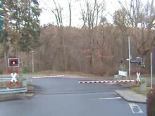
If a train passes the switch-on point of a level crossing, security must be guaranteed until the train arrives at the level crossing. The time it takes for the fastest train (at maximum line speed) to get from the switch-on point to the level crossing is called the approach time .
The level crossing must be secured within this time. The approach time for half-barrier systems is made up of the following components:
- Pre-lighting time
- Barrier closing time
- Remaining time
The pre-lighting time includes the time of yellow and red illumination (with flashing light systems, the flashing of the red light) until the barriers close. According to the RiLSA , the yellow illumination should be three seconds (on roads with a maximum speed of 50 km / h) to five seconds (at 70 km / h), depending on the maximum permitted speed . The pre-lighting time should be at least twelve seconds. This is to ensure that the level crossing can be safely cleared before the barriers close. Depending on the local conditions, a longer period of time must be set for this. Reasons can be B. very wide level crossings, level crossings with acute crossing angles or level crossings in the vicinity of retirement homes or the like. be.
The barrier closing time of electric barrier drives is usually given as six seconds for barrier booms with a length of up to six meters, otherwise with ten seconds.
The remaining time is intended, on the one hand, to ensure that the driver does not see any open or just closing barriers when approaching. Otherwise, he could initiate an emergency stop for fear of not closing the barrier in time. In addition, for psychological reasons, one would like to avoid the train arriving directly after the barrier closes. The sense of security of the drivers and the train drivers is thereby strengthened. The remaining time should be at least eight seconds.
This results in a minimal approach time (under favorable circumstances) of 26 seconds. It is made up of twelve seconds of pre-lighting time, six seconds of barrier closing time and eight seconds of remaining time. The switch-on point must be selected so that even the fastest train needs at least 26 seconds from the switch-on point to the level crossing.
In the case of traffic lights, the approach time is the value that the road user needs to drive through the blocked route plus four seconds of safety surcharge. The approach time must be at least twenty seconds.
A modern level crossing with half barriers and light signals (yellow / red) should have an approach time of a maximum of 240 seconds in Germany. The approach time is the time from when the level crossing is switched on until the first train enters the level crossing. If this time calculated during planning is exceeded, e.g. B. through complex track systems, train stations or stops in the approach route, a level crossing system should be designed as a full closure. Likewise, by taking suitable measures, walking past or driving past the half-barriers, e.g. B. by a roadway divider can be prevented. Although bypassing or crossing a closed level crossing system is a violation of StVO § 19, the "240-second rule" is intended to prevent a source of danger from arising during the planning phase. This planning principle does not mean that the level crossing may be crossed after this time, although it is closed. In this regard, level crossings that are covered by main signals are particularly problematic, because they should be switched on so early that a driver already passes the main signal or an occasional distant signal in the driving position in order not to brake unnecessarily.
A disturbed level crossing may generally only be crossed if an employee of the railway or the federal police allows the crossing. According to the current legal situation, the state police are not entitled to allow a crossing (BPolG § 3 and EBO § 11).
With Lo systems, it must also be ensured that the monitoring signal lights up for seven seconds so that the driver can perceive it. The monitoring signal is switched on as soon as the red light lights up on all road signals (not only when the barriers have been closed), so that the time required from the switch-on point to the monitoring signal must also be at least seven seconds + yellow time. In addition, the monitoring signal must be in the braking distance. If this is longer, the approach time increases. The higher value then applies.
High-speed travel at level crossings (1977 to 1992)
Between 1977 and 1988, the Federal Minister of Transport - in deviation from the EBO regulations at the time - exceptionally permitted driving on railway lines at 200 km / h; this exception also included level crossings. The German Federal Railroad also regulated the use of level crossings at over 160 km / h as part of a high-speed guideline. At that time there were still numerous such crossings on the upgraded routes. With the third EBO amending ordinance of May 1991, the maximum speed limit for passenger trains was increased from 160 to 250 km / h. At the same time, level crossings for speeds of more than 160 km / h were banned. Article 2 of the ordinance provided for a transition period for existing level crossings on high-speed lines, which allowed existing level crossings to be driven on at speeds between 160 km / h and 200 km / h until December 31, 1992. The barrier booms at the level crossings concerned were monitored by a conductor loop (tree break loop) in the event of road vehicles breaking through. In addition, the covering signals were switched in such a way that they could only be set to travel when the barriers were closed.
In 1994, Deutsche Bahn AG proposed to revoke this exemption and leave the decision to drive on level crossings at over 160 km / h to the company's board of directors. The company justified its proposal by making rail transport more attractive through the speed increases that it made possible. Technical safety measures could achieve the same level of safety at high-speed crossings as could be achieved with the other crossings. Furthermore, since 1977 there has been no accident at a high-speed railroad crossing. An alternative proposal by the DB provided for high-speed journeys to continue to be permitted at least at those level crossings, the removal of which is particularly difficult in terms of planning or economics, for example on subordinate roads outside built-up areas. Such transitions could be equipped with additional technical security elements. A working group of the Federal Ministry of Transport, with the participation of DB AG and VDV , rejected the company's proposal.
Behavior of road users at level crossings

In Germany, the Road Traffic Regulations (StVO) regulate the behavior of road users at level crossings.
Road signs announce a level crossing so that road users can recognize it in good time. Approximately 240 meters in front of the level crossing, three-lane beacons are usually set up on both sides of the road, on which the danger sign “level crossing” (formerly also “restricted level crossing”) is attached. Behind it, at a distance of 160 meters, are two two-lane beacons and 80 meters before the St. Andrew's Cross, two single-lane beacons. The distances between the beacons can also differ; these are then indicated with the corresponding meter information on the beacon.
Road traffic is only allowed to approach a level crossing carefully, ready to brake and at moderate speed. Anyone driving a vehicle is not allowed to overtake vehicles at level crossings from signs 151, 156 up to and including the intersection of rail and road.
Vehicles have to wait in front of the St. Andrew's Cross, pedestrians at a safe distance in front of the level crossing, if
- a rail vehicle is approaching,
- red flashing light or yellow or red light signals are given,
- the barriers are lowering or closed or
- a railway employee orders a stop.
- an audible signal, such as a whistle signal from the approaching train, sounds.
Roads entering the street must not be blocked while waiting, combustion engines should be switched off if the vehicle is stopped for a long time. At night it is important that oncoming traffic is not dazzled and that this overlooks the closed barriers or the red or flashing light. The high beam must be switched off in any case, and the low beam as well.
- Signs in front of level crossings

Sign 156: three-line beacon with sign 151 (about 240 meters before the level crossing)

Sign 159: two-lane beacon (about 160 meters before the level crossing)

Sign 162: single lane beacon (about 80 meters before the level crossing)
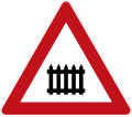
Sign 150: Gated level crossing (valid until 2013)

Sign 151: Unrestricted level crossing (FRG, 1971–1992)

Image 12: Unrestricted level crossing (GDR, 1964–1977); almost identical until 1971 also in the FRG
_vor_unbeschranktem_Bahn%C3%BCbergang,_StVO_1992.svg)


Driving on is only permitted when the barriers are fully open, no more lights are on and no rail vehicles are approaching, not even from the opposite direction. The level crossing must then be crossed quickly and without stopping, but the speed must be adapted to any bumps in the road. If the level crossing cannot be crossed when there is a backlog, road users must wait in front of the St. Andrew's Cross until the traffic jam has cleared and it is possible to drive over the level crossing safely without interruption .
Waiting at a level crossing is prohibited. It is forbidden to stop up to ten meters in front of and behind the St. Andrew's Cross if this obscures the view of it. Parking is prohibited in built-up areas up to five meters, outside built-up areas up to fifty meters in front of and behind the St. Andrew's cross.
For special features of a call barrier, see there.
Two-wheelers can avoid falls if they cross the track at as right an angle as possible.
Administrative offense, fine
Anyone who intentionally or negligently violates one of the rules for behavior at level crossings commits an administrative offense according to Section 49 of the Road Traffic Regulations and can be fined for this . The relevant facts include not only crossing a level crossing with a yellow or red light or red flashing light, but also failure to observe the priority of rail traffic in other situations, such as crossing a level crossing that is not technically secured even though a rail vehicle is approaching.
The fine can be levied on road users if they
- violate the aforementioned waiting obligations before a level crossing,
- with a vehicle disregard the priority of a rail vehicle or
- crossing a level crossing in breach of the obligation to wait or
- Do not follow a red alternating light sign or a red continuous light sign.
The regular fine is between 70 and 700 euros
The catalog of fines regulation mentions in the section “deliberately committed administrative offenses” under serial number 244/245 the offense “level crossing despite closed barrier or half barrier crossed” as an offense subject to the highest penalty: “When driving a motor vehicle”, 700 € are to be paid and 3 months driving ban, “When walking, cycling or as another non-motorized person participating in traffic” 350 €.
literature
- Siegfried Giesa, Stefan Bald: HAV: Instructions for attaching traffic signs and traffic facilities. 12th edition, Kirschbaum, Bonn 2003, ISBN 978-3-7812-1700-3
- Helmut Kranz: 1843-1983. 140 years of the Hanover Railway Directorate. Federal Railway Directorate Hanover, Hanover 1983, p. 91ff.
- Erich Preuß: Level crossings of German railways since 1835. Transpress, Stuttgart 2014, ISBN 978-3-613-71481-6
- Ferdinand Hein: Sp Dr 60 signal boxes operate , Eisenbahn-Fachverlag Heidelberg-Mainz, ISBN 3-9801093-0-5
- Instructions for attaching traffic signs and traffic facilities , HAV 12th edition, Kirschbaum Verlag GmbH Bonn
- Georg Kerber and Andreas Stirl: Signals and contact lines on model railway systems, Transpress Verlag, ISBN 3-613-71075-7
- Federal Railway Directorate Hanover: 1843-1983. 140 years of the Hanover Railway Directorate. Hannover n.d. (1983), page 91 ff.
- Andreas Braun: Signals from the German railways. GeraMond Verlag , Munich 1999, ISBN 3-932785-14-2
- Ferdinand Hein: Operate Sp Dr 60 signal boxes. Part A: In regular operation. 3rd edition, Eisenbahn-Fachverlag, Mainz 2000, ISBN 3-9801093-0-5
Web links
- "Looked? Safe over it! ”- Correct behavior at level crossings , accident prevention campaign by Deutsche Bahn, ADAC, the federal police and the statutory accident insurance companies VBG and UVB
- Clear description of the functionality of level crossings
- Basics of level crossing protection as well as examples for switch- on sections on the IfEV homepage of the TU Braunschweig
- Presentation page of the level crossing technology manufacturer Scheidt & Bachmann with information on the individual components
- Level crossing at Laurenburg with 2-train display and alarm clocks on YouTube , video (1 minute 58 seconds)
Individual evidence
- ↑ a b Accident numbers at level crossings have more than halved since 1996 . In: DB World . Regional part west. December 2007, p. 23 .
- ↑ Existing level crossings. (PDF; 999 KiB) (No longer available online.) Deutsche Bahn AG, 2012, archived from the original on January 14, 2016 ; accessed on December 1, 2017 .
- ↑ Infrastructure status and development report 2019. (PDF) Performance and financing agreement II. In: eba.bund.de. Deutsche Bahn, April 2020, p. 132 , accessed on May 17, 2020 .
- ^ Wilhelm Cauer: Operation and traffic of the Prussian State Railways. A manual for authorities and officials. First part. Julius Springer, Berlin 1897. pp. 74, 99.
- ↑ Cauer, p. 197 f.
- ^ Announcement regarding the operating regulations for the main railways in Germany . In: German Reich Law Gazette . tape 1892 , no. 36 , p. 747-763 ( Wikisource ).
- ^ Announcement regarding the operating regulations for the main railways in Germany . In: German Reich Law Gazette . tape 1892 , no. 36 , p. 764-785 ( Wikisource ).
- ↑ Railway translation. In: Viktor von Röll (ed.): Encyclopedia of the Railway System . 2nd Edition. Volume 1: Cover - discontinuation of construction . Urban & Schwarzenberg, Berlin / Vienna 1912, p. 433 f.
- ↑ a b c Ernst Kockelkorn: Effects of the new railway building and operating regulations (EBO) on railway operations . In: The Federal Railroad . tape 41 , no. 13/14 , 1967, ISSN 0007-5876 , pp. 445–452 ( Drahtkupplung.de [PDF]).
- ↑ The Unification Agreement stipulated in Annex 1 in Chapter XI (Division of the Federal Minister of Transport), Section A: Railway Transport, Section III, No. 6 in Letter a: “For existing installations, the bodies named in Section 3 can ensure that railway regulations continue to apply -Building and operating regulations of July 17, 1928 (RGBl. II p. 541), last amended by ordinance of July 23, 1943 (RGBl. II p. 361), to permit until December 31, 1993. ”Original text of the Unification Treaty ( Federal Law Gazette 1990 II p. 885 (PDF, page 214) or on buzer.de ), so the final elimination of the name cannot be clearly assigned to 1990.
- ^ Text of the BOStrab 1965. In: private website. Retrieved October 26, 2017 .
- ^ Text of the BOStrab 1969. In: private website. Retrieved October 26, 2017 .
- ↑ a b Fewer accidents at level crossings , answer (19/3254) by the Federal Government to a small question from the Die Linke parliamentary group in the German Bundestag, July 17, 2018.
- ↑ Adolf Rebler: Principles of liability in traffic accidents at level crossings . In: Road Traffic Law - SVR. Journal for the practice of traffic lawyers , ISSN 1613-1096 , vol. 10 (2010), pp. 441–447, here p. 441 ( PDF ).
- ↑ here page 1111 . In: Federal Law Gazette . 30, part 1. Bonn May 16, 1991, p. 1098-1111 .
- ↑ here page 1100 . In: Federal Law Gazette . 30, part 1. Bonn May 16, 1991, p. 1098-1111 .
- ↑ Dirk Kolling: The way to today's level crossing safety technology . In: Yearbook of the Railway System 2010. 175 years of railways in Germany. Pp. 118-121; here: p. 120.
- ↑ E. Behr: Securing path crossings at rail height . In: VDI-Zeitschrift , 34 Volume 82, (1939), p. 965 ff .; here: p. 969.
- ↑ a b Reichsverordnungsblatt 1, 1936, Edition B, Motor Transport No. 1
- ↑ Heinrich Korner: New warning lights for unrestricted level crossings . In: Elektrotechnische Zeitschrift Edition B (Der Elektrotechniker), 2, (1953), p. 54.
- ^ Richard Meyer: Structure and changes in railway law . In: Public Administration. Journal of Administrative Law and Administrative Policy, 1950, pp. 420–424; here: p. 424; Heinrich Korner: New warning light systems for unrestricted level crossings . In: Electrotechnical Journal . Edition B (Der Elektrotechniker), 2, (1953), p. 54.
- ↑ Germany in reconstruction. Federal government activity report for 1953 . Bonn 1954, p. 216.
- ↑ a b c d e here page 2422/3 . In: Federal Law Gazette . 61, part 2. Bonn December 28, 1960, p. 2421-2423 .
- ↑ a b DB head office: More and more security at level crossings . In: Bulletin of the Press and Information Office of the Federal Government , No. 149, August 12, 1960, Bundes-Verlag, 1960, p. 1484.
- ↑ The last level crossings with illuminated letters "2 ZÜGE" . In: turntable . tape 38 , no. 304 , June 2020, ISSN 0934-2230 , ZDB -ID 1283841-X , p. 98-100 .
- ^ Heinz Delvendahl: The railway systems in the new railway building and operating regulations (EBO) . In: The Federal Railroad . tape 41 , no. 13/14 , 1967, ISSN 0007-5876 , pp. 453-460 .
- ^ A b c d Walter Mittmann, Fritz Pätzold, Dieter Reuter, Hermann Richter, Klaus-Dieter Wittenberg: The Third Ordinance to Change the Railway Construction and Operating Regulations (EBO) . In: The Federal Railroad . tape 64 , no. 7-8 , 1991, ISSN 0007-5876 , pp. 759-770 .
- ↑ provision for securing railroad crossings at non-federal own railways (BÜV-NE) system 8 to Section 12 (6) a), BÜSTRA = B ahn ü transition and road ßensicherung "Guidelines on dependencies between the technical safety of railway crossings and the traffic control at the adjacent Intersections and junctions "
- ↑ a b c Regulation for securing level crossings on non-federal railways , VDV 2001, Annex 9c "Special switching cases for level crossings in rapid succession", cases 5 and 6.
- ↑ a b c d Kolling, Dirk: The way to today's level crossing safety technology. In: Yearbook of the Railway System 2010, pp. 2–5. Online version of the article on the Pintsch Bamag website, PDF (593 KB)
- ↑ Aussem, H .: NE BUE 90e - a computer-aided level crossing system for non-federal railways, in signal and wire; 83, 12 (1991); Pp. 287-292; ISSN 0037-4997
- ↑ a b c d German Federal Government: Review of legal provisions and regulations to relieve and improve the economic results of the railways (PDF; 721 KiB). Bundestag printed matter 8582, October 18, 1994, point 10, pp. 7-9.
- ^ Karlheinz Rößler: Speed limit for the IC - but not for German speeders . In: rail . tape 12 , no. 1 , 1993, ISSN 0932-2574 , pp. 21-24 .
- ↑ Jürgen Grübmeier, Georg Fischer: The expanded lines of the German Federal Railroad . In: The Federal Railroad . tape 57 , no. 10 , 1981, ISSN 0007-5876 , pp. 781-788 .
- ^ [1] Fine - level crossing, accessed August 26, 2014.
- ↑ of March 14, 2013 (Federal Law Gazette I p. 498) [2]