
Gray code
| Gray code | |
|---|---|
| steadily | Yes |
| Hamming distance | 1 |
The Gray code is a continuous code in which neighboring code words differ only in a single binary digit, the Hamming distance of neighboring code words is 1.Transmission errors in continuously changing digital signals on multi-core lines are reduced in this way, as different delay times are not reduced can affect. It serves as a coding method for the robust transmission of digital quantities via analog signal paths. The code is named after the physicist Frank Gray , who received the patent for this process in 1953 .
The Gray code is usually implemented as a binary code , but it can also be used for multi-level transmission paths.
Generation from binary code
Logical operators
The following points show how to get a Gray-coded binary number from a binary code step by step:
- X1: binary number in binary code
- X2: Right shift of the binary number by 1 bit
- X3: Modulo-2 addition ( XOR operation ) of X1 and X2; this is the desired number in the gray code.
The same as pseudocode:
- Binary code X1 → Gray code: X3 = (X1 XOR X2)
And as a formula:

Generator matrix
Since the Gray code is a linear code , it can be generated with a generator matrix . A binary word of length can be viewed as a vector of a -dimensional -vector space . Let us now be a line vector, then the coding of the word into the code word can be represented as follows:


The decoding is done by multiplying the inverse of . This has the following form:


The vector space can be clearly represented with hypercubes .
Generation as a gray counter
You can also program a Gray code counter directly in hardware (e.g. in HDL ). To do this, it is helpful to use an auxiliary register that toggles with every clock cycle.
 Qh [n+1] = !Qh [n]
 Qh [0  ] =  0     wenn der Gray-Code-Zähler mit Null startet also Q[0]=0, oder Q[0] eine gerade Anzahl an Einsen hat. Bei anderer Initialisierung würde der Zähler rückwärts laufen.
This makes the combinatorics quite clear:
 Q0  [n+1] = !(Q0  [n] ^   Qh  [n] )
 Q1  [n+1] =   Q1  [n] ^ ( Q0  [n] &  Qh  [n] )
 Q2  [n+1] =   Q2  [n] ^ ( Q1  [n] & !Q0  [n] &  Qh [n] )
 Q3  [n+1] =   Q3  [n] ^ ( Q2  [n] & !Q1  [n] & !Q0 [n] & Qh [n] )
           …
 Qk-1[n+1] =   Qk-1[n] ^ ( Qk-2[n] & !Qk-3[n] & …  & !Q1 [n] & !Q0 [n] & Qh [n])
 Qk  [n+1] =   Qk  [n] ^ (!Qk-2[n] &            …  & !Q1 [n] & !Q0 [n] & Qh [n])
The difference between the formula for the largest bit Q k and the smaller bits Q k-1 is necessary so that the counter is cyclical, i.e. the counter jumps to the initial value Q = 000 ... 00 after the last value Q = 100 ... 00. With an infinite counter, there would be no difference.
 ^ := Exklusiv Oder / XOR / Antivalenz

 ! := Inverter / NOT / Negation

 & := Und / AND / Konjunktion
meaning
The motivation for the development of this code is the following problem: On several cores of an electrical data line, data are to be transmitted in parallel that change continuously (i.e. always by only one digit). B. Signals from a temperature sensor or a rotary encoder . Transferred as a binary number, the bits theoretically change exactly at the same time for a new measured value on each affected line, both at the input of the line and at the output. In fact, however, the bits on the line do not change at the same time. This can have various causes: component scatter, running times, asymmetries, etc. This leads to undesired intermediate states and briefly (between the red lines) incorrectly received values:
|
|
Problem with dual code signals

While the theoretical signal in the order
- {0000}, {0001}, {0010}, {0011}, {0100}, {0101}, {0110}, {0111} etc.
is sent, other signal states briefly arrive at the output:
- {0000}, {0001}, {0000} , {0010}, {0011}, {0100}, {0101}, {0111} , {0110}, {0111} etc.
Solution with Gray code

To avoid this, the control signal states are sent using a Gray code, so that only one bit changes at a time:
- Sent sequence: {0000}, {0001}, {0011}, {0010}, {0110}, {0111}, {0101}, {0100} etc.
- Incoming sequence: {0000}, {0001}, {0011}, {0010}, {0110}, {0111}, {0101}, {0100} etc.
The same sequence then arrives at the output as at the input even if considerable time errors (red lines) occur.
Karnaugh-Veitch diagram
In the Karnaugh-Veitch diagram , the Gray code can be recognized - several sequences are possible - from the fact that transitions only occur between (horizontally or vertically) neighboring fields.
|
|
The code is also suitable for cyclic applications such as the disk shown below, as only one digit changes when changing from the highest number to zero.
The value of a 1 at the position in the Gray code number system is (where n counts from 1, so… 31, 15, 7, 3, 1). In contrast to the normal binary system, the individual ones are not added, but subtracted starting from the right. Example: 111 Gray = 7 - (3 - 1) = 5 or 1111 Gray = 15- (7 - (3 - 1)) = 10. Digits that are 0 are left out, example: 101 Gray = 7 - 1 = 6.

The process of generating gray code is symmetrical.
Since neighboring values only differ in one digit, the Gray code is suitable for uncovering errors in serial processes.
Geometric and graph theoretical representation
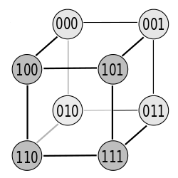
Image 1: cube

Image 2: Cube with coordinate system

Fig. 3: The 6 paths to the Gray code in the table. It is a Hamilton cycle . Starting point: 000 (green circle at the top left), continuation: green → blue → red → black line, end point: at the starting point


Figure 1 shows the hexahedron for 3 variables and Figure 2 the same cube with the associated coordinate system. The nodes (corner points or circles) on the unit cube each correspond to a line in Gray code. The transitions (neighborhood of the lines) are symbolized by the edges of the cube. A Gray code is created when walking on the edge.
| a) | b) | c) | d) | e) | f) |
|---|---|---|---|---|---|
| 000 | 000 | 000 | 000 | 000 | 000 |
| 001 | 100 | 010 | 010 | 001 | 100 |
| 101 | 101 | 110 | 011 | 011 | 110 |
| 100 | 001 | 100 | 001 | 010 | 010 |
| 110 | 011 | 101 | 101 | 110 | 011 |
| 111 | 111 | 111 | 111 | 111 | 111 |
| 011 | 110 | 011 | 110 | 101 | 101 |
| 010 | 010 | 001 | 100 | 100 | 001 |
Exactly 1 bit changes on each edge. The Gray code has as many neighborhoods as the cube has edges. From the cube in Figure 1, the possible paths can be traversed in 6 different ways. Thus there are 6 possibilities to generate a 3-bit Gray code that fulfills the conditions of the Gray code (table and figure 3). Apart from that, the Gray code is cyclical and the starting point could therefore also be on a different line. Because of its simple recursive generation rule, the binary reflected Gray code is usually specified (column “e” - penultimate column in the table). There is a whole class of Gray codes for a certain bit length.
There are exactly as many variants for an n-bit Gray code as there are Hamilton circles on an n-dimensional hypercube .
| a) | b) | c) | d) | e) | f) |
|---|---|---|---|---|---|
| 000 | 000 | 010 | 010 | 000 | 100 |
| 001 | 100 | 110 | 011 | 001 | 110 |
| 101 | 101 | 100 | 001 | 011 | 010 |
| 100 | 001 | 101 | 101 | 010 | 011 |
| 110 | 011 | 111 | 111 | 110 | 111 |
| 111 | 111 | 011 | 110 | 111 | 101 |
| 011 | 110 | 001 | 100 | 101 | 001 |
| 010 | 010 | 000 | 000 | 100 | 000 |
Since the Gray code shown here is cyclical, the code in columns c), d) and f) has been shifted one place up in this table (compared to the table above) so that the three zeros in the last line of the table. It can thus be seen that the Gray code in column a) is only a mirror image reversal of column b). Likewise, column c) is the reverse of column d), while column e) is the reverse of column f). There are three undirected Hamilton circles on the three-dimensional cube, which are shown here only in different directions (directed Hamilton circle).
For a better illustration, the code tables for the 6 variants of the 3-bit Gray code are shown here again. Whereby variant e represents the binary reflected Gray code, which is usually meant when the Gray code is mentioned. The 6 versions can also be generated by permutating the 3 columns of the code table. It follows that with n bits n! Versions there. So for 3 bit 3! = 6 versions of the 3-bit gray code.


| ... etc. ... |


The 4-bit Gray code can be read from the hypercube in Figure 4. There are 4 for 4 bits! = 24 different gray codes.
Applications


One possible application is the determination of the absolute position of a pane or strip, which is marked with black and white bars, which are scanned with light barriers or other sensors. This position is then used for angular or rotational speed measurement.
Another application is fringe projection . There a sequence of patterns made up of parallel strips is projected onto an object. The number of the stripes is Gray-coded and can be calculated for each pixel by an observing camera.
Another application is the asynchronous reading of data. For example, the Gray code is used to read the counter readings into correlators without errors. Even in the worst case, when reading in during a toggling bit, the result is always correct, because a toggling bit is not defined and it only makes a difference of ± 1. This type of reading requires no synchronization and very little CPU time.
Other possible applications are wind direction meters or water level meters, mapping of the car's height in elevators.
The reflected Gray Code has a close relationship with solving the problem of the Towers of Hanoi , and it also describes the solution of the Chinese rings .
example
The decimal number corresponds to the Gray code . Decoding in decimal notation then follows the rule . If more ones appear in a number of Gray code, they will be subtracted from each other: The Gray code is decoded as follows: .


General procedure: In a conversion, the position of the ones is crucial. The position affects the bill. If we look at the number 100, then the one is in position 3 (from right to left). The factor for one is obtained by considering the maximum number of decimal points that can be stored in binary form in a 3-bit number. A maximum of 7 (111) can be stored in 3-bit binary code. If we now take a larger binary number, it works practically analogously. Binary number: 11010 (1 in position 5.4 and 2). 5 bit binary number: max. 31 4 bit binary number: max. 15 2 bit binary number: max. 3
Calculation:

Recalculate a Gray code
  for I := NumBits - 1 downto 0 do        // jedes einzelne Bit vom letzten bis zum ersten
    Value := Value or (                   // das Ergebnis jedes errechneten Bits dem Gesamtergebnis hinzufügen
      (((1 shl (I + 1)) and Value) shr 1) // das Bit der Stelle zuvor im Ergebnis
      xor                                 // xor mit
      ((1 shl I) and GrayCode)            // der aktuellen Stelle des Codes
                       );
history
Even before the term Gray Code was introduced, there were already mathematical puzzle games in which the principle was applied. Only later did the code attract the attention of engineers. As early as 1878 Otto Schäffler, who produced and improved telegraphs and telephones in Vienna, used the reflected Gray code. The Frenchman Jean-Maurice-Émile Baudot used Gray codes for electrical telegraphy in 1887 . He received the French Legion of Honor for his work .
It was named after Frank Gray , a researcher at Bell Laboratories , who only rediscovered the code for his purposes in 1946. A patent for a Gray-encoding electron tube was granted on March 17, 1953, entitled Pulse Code Communications , U.S. Patent No. 2,632,058 .
Similar codes
Web links
- Java example for converting a decimal number into Gray code representation ( Memento from September 30, 2007 in the Internet Archive )
- Algorithms for generating the reflected Gray code on the Combinatorial Object Server
Individual evidence
- ↑ Patent US2632058 : Pulse code communication. Published March 17, 1953 , inventor: Frank Gray.
- ↑ U.S. Patent Number 2,632,058 freepatentsonline.com