Cascode
The cascode circuit (not to be confused with the cascade circuit ) is an electrical amplifier circuit with at least two electron tubes or transistors that are connected in series. The main advantage is the negligibly small Miller effect , which allows a higher bandwidth , but also high input and output resistance .
The word Kaskode is a suitcase word and originated in 1939 from the term “ Kask ade zur Kath ode ”, which is supposed to indicate the series connection of the two cathodes in the electron tubes originally used. The circuit was first described in 1939 in a paper by FV Hunt and RW Hickman for voltage stabilization .
Structure with tubes
In the historical implementation with electron tubes, it consists of two triodes , whereby the first stage - a normal cathode base circuit - is galvanically coupled to the second stage, a grid base circuit . As a result, this circuit combines two advantages: high input resistance with negligibly low feedback, because the control grid of the second tube acts as a shield. Since triodes are used, the noise is considerably lower than with pentodes , which is why this form was used as the input stage of the first television receiver (still equipped with electron tubes) .
Structure with transistors
The cascode circuit can also be formed with transistors as in the adjacent circuit diagram with bipolar transistors . Here the input transistor T1 works in common emitter circuit and the output transistor T2 in basic circuit with current control.
The second stage, the common base transistor T2, has a low input resistance at the emitter connection, which results in a small negative voltage gain of the first stage and greatly reduces the Miller effect. The effect of the output on the input is greatly reduced, especially in the high-frequency range, and the usable bandwidth of RC amplifiers in oscilloscopes increases considerably. The maximum output resistance is increased, while the input resistance with direct current remains almost identical to the emitter circuit.
The lower amplifier element only needs to have a low reverse voltage, while the upper one can have a high reverse voltage with a low current gain. This meets the specifications of many amplifier elements when it comes to switching high voltages quickly. Optimal properties are achieved if a power MOSFET is selected for T1 .
Combinations of transistor (below) and electron tube (above) are also possible, whereby the transistor achieves a voltage gain of approx. −100. This makes it possible to switch high voltages up to a few 10 kV without having to generate the high control voltage of the tube (a few 10 V).
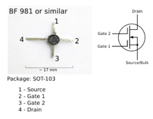
Dual-gate MOSFETs are integrated series circuits of two field effect transistors ; they have so little feedback that VHF amplifiers can be built with them without neutralization. In mixer stages of heterodyne receivers , the oscillator voltage is fed to the upper gate 2, which means that the MOSFET has properties similar to a hexode , but with considerably less noise.
Individual evidence
- ^ RW Hickman, FV Hunt: On Electronic Voltage Stabilizers , in Review of Scientific Instruments , Issue 10, pages 6-21, January 1939.
literature
- Manfred Seifart: Analog circuits. Verlag Technik, Berlin 1996, ISBN 3-341-01175-7
- U. Tietze, Ch. Schenk: Semiconductor circuit technology. Springer-Verlag, Berlin Heidelberg New York, ISBN 3-54016720-X
Web links
- The cascode circuit , hypermedia tutorial electronic circuits of the Institute of Electron Devices and Circuits at the University of Ulm
- Cascode connection , compound circuits with bipolar transistors


