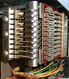
Coordinate switch

The crossbar switch is an electromechanical component of analog telephone switching technology . A coordinate switch is a kind of oversized relay with a system of crossed “bars” and “bridges”. Depending on which individual bar and bridge magnets are controlled in the coordinate switch, the contact sets located at their intersection switch through the desired connection. Compared to the rotary dial, this represents an improvement in the quality of the telephone connection. Noises have largely disappeared, and this mechanical dialing system requires little maintenance.
Areas of application
The development of the coordinate switch dates back to the 1930s. It was mainly used in the telephone exchange technology of the GDR. In the Federal Republic of Germany, the precious metal motor rotary selector (EMD selector) was used in the switching offices of the Deutsche Bundespost . In the FRG, the first exchange of this type was switched on in April 1955 in Beilstein ( Heilbronn node office area ) for test purposes. A further twelve switching centers were then put into operation. In the Bremerhaven hub area, another ten exchanges with crossbars were built by the end of 1959. However , the coordinate switch was widespread in telephone systems . Its solid construction (encapsulated in a sheet steel housing with a glass pane) gave the telephone system a high level of reliability with minimal maintenance.
functionality
Coordinate switches were used to switch telephone connections in so-called "indirectly" controlled switching systems, i.e. H. the dialing impulses that the calling subscriber sent with his dial did not “directly” set a voter (as for example with the EMD system) to the desired position, but were first counted by a special relay, the counting magnet . This counting magnet had ten small armatures, was very compact (space required for two flat relays 48 ), worked on the principle of the latching relay and was able to “count” up to ten pulses, which corresponds to the number “0” on the dial. In the switching systems of the GDR (e.g. ATZ64, S65, MSN70), counting chains of flat relays 48 were built up instead of the counting magnet.
Only after the electoral information for this electoral level had ended were the corresponding bar and bridge magnets of the coordinate switch switched on and the contact set located at the intersection point activated. For this purpose, so-called marker springs are located on the rods. These are spring-loaded thin pins (see pictures coupling point). Depending on the connection to be made, the rods are rotated slightly up or down by the electromagnets arranged on the side . This causes the marker springs to tip in the openings between the bridges (vertical bars) and the web (control plates made of plastic for the contacts). Then the electromagnet of the corresponding bridge is activated, causing the rod to tilt in the direction of the web and contact set. With the marker spring clamped between the bridge and the bridge, the bridge actuates the contacts. Finally, the rod goes back to its starting position, whereby the connection remains because the marker spring is clamped at the contact point. The connection is released by releasing the bridge, which opens the contact at the crossing point and the needle springs back into its rest position. Re-springing is minimized by a damping element on the marker pen (mostly loosely attached plastic part).
After setting up a connection, only one bridge is occupied; further connections can be set on other bridges.


