
Flat relay


The flat relay is one of the telecommunication relays and was a universally used switching element in electromechanical switching technology. It was the most popular relay there. Today it can only be found very rarely outside of museums.
General
The flat relay works on the principle of an electromagnetic relay ; it takes its name from the shape of its iron core , which has a flat, rounded rectangle in cross section (in contrast to the round relay with a cylindrical core). The flat relay has a standardized structure according to DIN 41220 and is intended for installation on relay rails in a fixed position.
This type of relay was developed by Siemens & Halske in 1925 and, after improvements, was used as flat relay 28 from 1928 . After 1945 the type was used in an improved form as flat relay 48 .
Coil windings
The flat relay 48 has six (in the older, non-standardized version - flat relay 28 - only five) solder pins. With galvanic isolation, up to three windings can be connected there, and even more with multiple assignment of connection pins. A distinction is made between magnetically effective and magnetically ineffective windings, so-called bifilar or resistance windings.
The most important values of the bobbin structure are given on the bobbin slip, a label attached to the bobbin. In detail these are:
- Specification of an optional delay winding
- Order of the windings, counted from the inside out, with Roman numerals
- Solder pin assignment (1–6 counted from top to bottom)
- Ohmic resistance of the winding at 20 ° C in Ω
- Number of turns
- Wire diameter in mm
- Conductor material, usually Cu for copper or Wd for resistance wire
- Type of conductor insulation, usually L for lacquer, 2L for two times lacquer, also S for silk
- Identification of an existing resistance winding with the addition bif
- Finally: The relay manufacturer's building regulations, e.g. B. SH Fg Bv 391/5257
Example of a coil specification on the coil slip:
- I (12) 2000-18900-0.10 CuL
- I = coil number
- (12) = solder pin assignment (beginning of wire is on pin 1, end of wire is on pin 2)
- 2000 = ohmic coil resistance in Ω
- 18900 = number of turns
- 0.10 = wire diameter in mm
- Cu = conductor material "copper"
- L = insulation material of the wire "lacquer"

Excitation winding
As a rule, enamel-insulated copper wires with a diameter of 0.05 to 1.0 millimeters have been used for the excitation windings; for a pick-up of the relay, depending on the number of contacts, 100 to 200 AW ( ampere-turns ), i.e. H. the product of the current through the coil and the number of turns. At 300 AW saturation is reached, so that further flow has no effect.
Resistance winding
Resistance windings are wound with two threads ( bifilar ) starting from the middle. The result is a parallel wire guide in which the current flows in opposite directions. As a result, the magnetic effect of the electric current is canceled out, the armature remains unaffected. Such windings could be used as a resistor in the circuit technology of telephone systems and exchanges . Because of the improved heat dissipation, these windings were attached last, outermost and mostly connected to solder pins five and six.
Differential winding
The differential winding consists of two separate windings with the same electrical and magnetic properties but opposite winding directions. This variant allows the relay to be controlled with current differences. In most cases, the differential winding consisted of three individual windings, with windings I and III being connected in series and winding II in between with opposite directions. This made it possible to avoid a different ohmic resistance in windings with the same number of turns but otherwise increased conductor length of the winding further out.
Delay winding

The delay or damping winding is a winding made of bare wire that is attached directly to the iron core. The ends of this winding were soldered directly to one another, i.e. not led out onto the connection pins. Such a winding results in a drop-out delay and also a pull-in delay of the relay. When the current in the excitation winding is switched off, the collapsing magnetic field in the short-circuit winding causes a current whose magnetic field, according to Lenz's rule, has the same direction as the collapsing field. This delays the dropping of the armature by 250 ms and more; at the same time, the pull-in time is increased slightly to around 60 ms.
If only a drop-out delay is to be achieved, this is achieved by short-circuiting a relay winding through a normally open contact of the relay.
contacts

The flat relay has up to three contact spring sets with up to five contact springs each. The assignment is designed so that the anchor is not loaded asymmetrically. With only one row of springs the middle row was used, with two rows the two outer ones. The 26 basic contact types according to DIN 40713 came into consideration as contact types. These were made up of the following six types of contact and their combinations (in brackets the older terms commonly used in telecommunications):
- Normally open (normally open contact)
- Normally closed (normally closed contact)
- Changeover contact with interruption (changeover contact)
- Changeover contact without interruption or subsequent changeover contact (subsequent changeover contact)
- Twin closer (twin working contact)
- Twin opener (twin rest contact)
Contacts in a spring set can be actuated simultaneously or one after the other when the armature is pulled.
The main contact material used was made of the following elements: silver , platinum , palladium , iridium , gold . For switching of extremely small currents (uA to 100 mA) were silver-platinum or gold-nickel alloys are used, while at higher switching voltages and currents (100-500 V; 0.5-8 A) and higher switching frequency alloys made of platinum and tungsten or palladium and copper or of pure tungsten were used.
See also
Web links
-
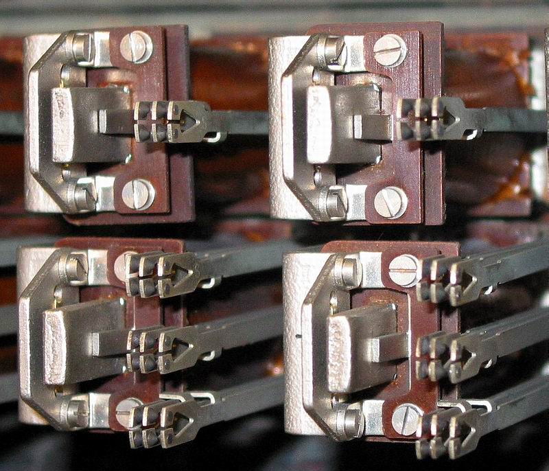
Picture of several flat relays 28
Note: The flat relays shown are the predecessor model "Flat relay 28". In this type, the twin contacts on each spring were designed as a V-shaped tongue (easy to see on the photo). In the case of flat relay 48, however, they were U-shaped, which allowed for easier adjustment. Furthermore, the three sets of contact springs were arranged parallel to one another in the flat relay 28. In the case of the flat relay 48, on the other hand, the outer sets of contacts were inclined towards the center at the front so that the actuating tabs of the individual springs could be safely reached by the armature actuating bar. - Main component of telephone systems Description Switching examples for drop-out delay and pick-up delay
- Flat relay at work video
Individual evidence
- ↑ a b c Harry Dittrich, Günther Krumm: Elektro-Werkkunde, Volume 5: Professional practice for telecommunications installers, telecommunications electronics technicians, telecommunications mechanics and telecommunications craftsmen with technical calculations and technical drawings. 5th revised edition. Winklers Verlag, Darmstadt 1973.
- ↑ a b c Horst Fleischer (ed.): Textbook of telecommunications technology . Founded by Karl Bergmann. Schiele & Schön, Berlin 1973.