
Parallelogram of forces


The parallelogram of forces is an aid for the geometrical investigation of forces . It is based on a law of mechanics that says:
- Any two forces acting at the same point can be replaced by a single force. This resulting force (also called total force or equivalent force ) has the same effect as the two initial forces combined.
As a geometric solution, one draws two force vectors with magnitude (i.e. a certain length) and direction as arrows. In the parallelogram that can be drawn from these two arrows, the diagonal from the point of origin shows the resulting force. Mathematically, this corresponds to the vector addition of the two force vectors . The reverse of this process is the decomposition of forces, in which a given force vector is split into two forces. In principle, any number of solutions are possible. If you know the direction of action of the decomposed components, there is exactly one solution and you can determine the amount of the two forces.
The law of the parallelogram of forces has an axiomatic character: It cannot be replaced by other laws - e.g. B. Newton's Laws - can be proven, but is assumed to be true because its results agree with practical experience. It is sometimes referred to as Newton's fourth law.
According to the same law, speeds are added in classical mechanics (see classical addition theorem of speeds ).
The expansion of the concept from the parallelogram of forces to more than two forces leads to a force corner . However, more than two forces can also be combined with the force parallelogram. For this purpose, two forces are first combined and their resultant is then combined with another force to form a new resultant. The process is then repeated until only one force remains.
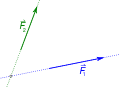
Graphic addition of two forces
A resultant force can be determined with graphic means, the effect of which on the body corresponds to the two initial forces.
- True-to-scale marking of the forces according to the point of application, amount and direction.
- Move the arrows along the line of action to the common point of intersection. If the two forces do not have the same point of application, the parallelogram of forces cannot generally be used. However, if the forces act on a rigid body , their effect does not change if they are shifted along their lines of action (so-called line volatility law ). It is often assumed that the forces act on a rigid body.
- Parallel displacement of the two lines of action, so that the line runs through the tip of the other force vector.
- The diagonal of the parallelogram created in this way forms the resulting force and replaces the two initial forces. The resulting force can be shifted along its line of action for further investigations if it acts on a rigid body.
Step 1

step 2

step 3

Step 4


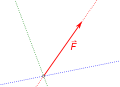
Graphic breakdown of forces
To make it easier to examine, a force is split into two partial forces that intersect at the same point. The amount of force components can be determined with graphical means based on the required direction of action.
- True-to-scale recording of the initial force and the lines of action of the partial forces
- Displacement of the initial force along its line of action to the intersection of the lines of action
- Parallel displacement of the lines of action of the partial forces so that the line passes through the peak of the initial force
- The side edges of the parallelogram that lie against the point of application correspond to the force vectors of the partial forces.

Step 1
step 2

step 3

Step 4


history
The law of the parallelogram of forces was first formulated in 1586 by Simon Stevin (1548–1620). Exactly a hundred years later, Isaak Newton (1643–1727) gave it in his Principia Mathematica not as an axiom, but as an addition. It was therefore based on its validity.
Web links
- Interactive Java applet for dismantling forces
- Force addition and decomposition at student level ( LEIFI )
Individual evidence
- ^ Böge, Böge: Technische Mechanik , Springer, 31st edition, 2015, p. 8.
- ↑ Dankert, Dankert: Technische Mechanik , Springer, 7th edition, 2013, p. 4.
- ^ Gross, Hauger, Schröder, Wall: Technische Mechanik 1 - Statik , Springer, 11th edition, 2011, p. 21f.
- ↑ Böge, Böge: Technische Mechanik , Springer, 31st edition, 2015, p. 9.
- ↑ Mahnken: Textbook of Technical Mechanics - Statik , Springer, 2012, p. 41.
- ↑ Bartelmann et al .: Theoretische Physik , Springer, 2011, p. 11.