Moving Target Indication
Moving Target Indication , MTI for short , is a term that comes from the English language and is anchored worldwide in the field of radar target acquisition. The " M oving T arget I ndicator" (also SBZ, selection of moving targets) called an assembly to "clutter suppression" in radar equipment. Since coherent signals are processed in this module , it is also called the coherent channel .
Slowly moving or immovable objects , mostly the landscape or stones, rocks, are masked out or “suppressed” from the display on the “ PPI-scope ”, ie the radar screen , with this MTI process ; only themselves remain Objects moving relative to the radar in the display. This filters out disturbances such as land vehicles, railways, other metallic reflecting objects, if desired and allows e.g. B. the display only of objects that are faster than a pre-adjustable relative speed to the observer radar.
Usually Doppler frequency methods are used. There are two ways of using the Doppler frequency to distinguish a moving object from an immovable one:
- direct measurement of the Doppler frequency (fast Fourier analysis )
- indirect measurement of the Doppler frequency by measuring and comparing the phase position.
Doppler frequency for radar
The Doppler effect also occurs with a moving object (the "target") observed by a radar device. The frequency shift of the transmission frequency due to the Doppler effect is a measure of its radial velocity . However, the Doppler effect occurs twice in a radar device. Once on the way from the radar antenna to the moving object. If a radar warning receiver in the aircraft were to receive this signal, then the transmission frequency plus a Doppler frequency would be measurable here, because the aircraft is moving towards the radar device, for example. The signal with this frequency is now reflected on the aircraft surface. This reflected energy (transmission frequency plus the Doppler frequency of the way there) experiences a second Doppler shift on the way back. So double the Doppler frequency arrives at the radar receiver.
As an approach to deriving the formula, the phase shift of the high-frequency signal can be taken as the ratio of the wavelength of the radar transmitter to the distance covered (2 · r) of the electromagnetic wave.
Pulse pair processing
When the aircraft moves towards the radar device, the path length r has also changed from the transmission pulse to the transmission pulse. Therefore, if the target is moving at a radial speed, each echo signal is received with a different phase position.
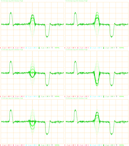
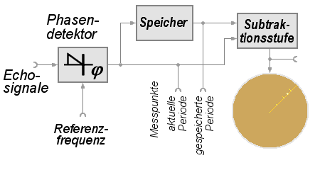
The Moving Target Indicator assembly must now be able to recognize this phase change. Here, two to three pulse periods are compared with one another and phase differences in the echo signal are evaluated. The procedure is also called "pulse-pair-processing" (in German: inter-period compensation). If the phase position of the echo signal remains constant from pulse period to pulse period, it is a fixed target. If the phase position is variable, then it is a moving object.
In practice, a complete pulse period, i.e. a deflection on the display device, has to be stored in a suitable assembly in order to compare it with the following pulse period. With two pulse periods, the comparison consists of a simple subtraction and amplification of the difference. Target characters that have no phase shift are thus canceled. Target characters that are moving have a phase shift and thus an amplitude difference at the output of the phase detector and are displayed on the display device.
In the history of radar devices, the memory was initially designed as an analog potential storage tube that wrote an entire period in a spiral on a layer of cesium. Later small capacitors were used as storage: the distance here already in small digital steps ( range cells ) and the amplitude still analog as capacitor charge (example: PRW-13 ). With the use of digital memories from data processing, this assembly was built entirely digitally. Today, the entire assembly is often just a software module in the Radar Data Processor , which, however, has to work exactly like its hardware predecessor in the program sequence : save a complete pulse period and compare the amplitudes with the current pulse period.
Doppler filter
A separation of the echo signals from clutter and from targets according to frequencies is difficult in analog systems because the Doppler frequencies that occur are very small in relation to the transmission frequency. The occurring Doppler frequencies can only be separated and recognized in digital signal processing systems. Both low-pass circuits (“zero-Doppler filter ” and “clutter-Doppler filter”) and filters with specified frequencies (“Doppler filter”) can be used that represent a certain radial velocity in the radar system .
The “Doppler filters” are connected in parallel to form a block for eight different Doppler frequencies, for example, and give an output signal when a Doppler frequency is detected that fits into the filter scheme. Modern digital Doppler filter banks achieve a number of more than 1000 different parallel filters. In this way, special targets such as helicopters in the stationary state can also be recognized and identified using their Doppler spectrum, which reflect a mixture of different Doppler frequencies.
Disadvantages of the procedure
- The procedure significantly reduces the sensitivity of the receiving tract and should only be switched on in areas where clutter occurs, for example in the close range or in the lower elevation angles (low beam).
- Objects that are far away from the observing radar and fly tangentially past the radar have too low a radial speed and are therefore also suppressed.
- Due to the periodicity of the oscillations, it can happen that the phase shift of the echo signal has a multiple of 360 ° and thus has the same value as 0 °. This is then referred to as a blind speed , which has to be suppressed by additional circuit measures in pulse pair processing.
- Large volume targets ( clouds ) can also receive a Doppler frequency from the wind and are then also shown on the display. A wind compensation can partially solve this problem.
- Wind turbines in the vicinity of radar devices interfere with the radar image because the movement of the windmill blades generates a strong Doppler frequency.
- The need to send multiple pulse periods in the same direction causes problems with the timing of radars. Therefore, in modern radar devices for the MTI method, greatly shortened pulse periods are often used, which again limits the application to the close range.
Individual evidence
- ↑ interim period compensation to www.radartutorial.eu
- ↑ Helicopter identification on www.radartutorial.eu


