Open circuit
In electrical engineering, open circuit refers to the outputs of electrical circuits that can assume a high-resistance (“open”) state. In this state, the connected lines do not carry any electrical potential specified by the output . Instead, they ideally behave as if they were just disconnected from the circuit. In practice, electrical components are never completely open (no infinite resistance) or closed, but also have a low contact resistance when closed and also have parasitic capacitances and inductances . In this article, the description of ideal components is assumed.
Output circuits
All of the techniques presented below serve the purpose of using multiple outputs (e.g. from different modules) on a common line (e.g. a bus line).
Open collector / open drain
Output circuits with open collector ( English open collector ), this designation is common with bipolar transistors , and the designation of the open drain ( English open drain ), common with field effect transistors , connect the connected signal line with a supply potential when active. In the inactive state, the output of the circuit is high-resistance so that the potential of the signal line is not affected.
When active, the output of NPN bipolar transistors or N-channel field effect transistors represents a direct connection to the lower potential (ground, GND). With PNP bipolar transistors or P-channel field effect transistors, a direct connection to the positive supply potential (V cc ) manufactured.
Such outputs are used together with a pull-up resistor, which applies the high potential to the output when inactive. The slow rising signal edge, which occurs because the relatively high resistance requires a certain amount of time to charge the (parasitic) capacitances of the output and connection line, is a disadvantage here.
There is not necessarily a higher-level authority that determines which output is allowed to work. This technology is used for. B. with the I²C bus .
Tristate
Tristate output circuits connect the connected signal line either to the higher potential, the lower potential, or they leave them unaffected, i.e. they have three states. In integrated circuits, the high-resistance state is controlled by a special enable input and is also referred to as Tri-Z . In the inactive state, the output of the circuit is highly resistive, so that the potential of the signal line is not affected.
In the equivalent circuit diagram for this high-resistance state, the output can be omitted entirely. When active, the output represents either a direct connection to the lower or the higher potential.
When using tristate outputs you need an instance that defines which output is active. In the case of a microprocessor bus, for example, this is an address decoder which (depending on the address on the address bus) selects one of the modules via the enable lines, which then activates its output or outputs.
Sustained tri-state
An output with sustained tri-state is in a way a hybrid of tristate and open collector. If the circuit of a module wants to deactivate an output, it puts the output at high potential for a short time before the output line is fully enabled. As a result, the output line is immediately set to high potential, without the pull-up resistor having to charge the parasitic capacitances. The other modules must observe the output and, if necessary, wait for the active phase before activating the output so that no more than one active circuit is working on the line - otherwise there would be malfunctions if a module wants to release the output line while it is is still held at low potential by another.
This method is used for. B. the PCI bus .
Wiring of the signal lines
Pull down
In electrical engineering, pull-down refers to a (relatively high-resistance) resistor that connects a signal line with the lower voltage potential. It brings the line to the low potential in the event that no output actively brings the line to a higher potential. Usual values are in the range from 1 kΩ to around 10 kΩ.
Pull up
In electrical engineering, pull-up refers to a (relatively high-resistance) resistor that connects a signal line with the higher voltage potential. It brings the line to the higher potential in the event that no output actively brings the line to a lower potential. Usual values are in the range from 1 kΩ to around 10 kΩ.
Pull-up-down
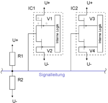
Pull-up-down circuits in the case of three-valued signal lines connect them to both the higher and the lower potential. By dimensioning the resistors as a voltage divider , the line is brought to a desired center potential in the event that no output actively brings the line to a higher or lower potential.
Symbols according to the IEC standard
| symbol | description |
|---|---|
 |
Normal, instantaneous exit |
 |
General sign for an "open exit", e.g. B. the open collector output |
 |
Open output H-type with low-resistance H-level and high-resistance L-level Wired-OR links are possible with these outputs . An external pull-down resistor must also be connected to the wired OR connection. |
 |
Open L-type output with high-impedance H level and low-impedance L level Wired AND operations are possible with these outputs . An external pull-up resistor must also be connected to the wired AND connection. |
 |
General sign for passive pull-up resp. Pull-down output |
 |
Passive pull-up output with H level through pull-up resistor and low-resistance L level |
 |
Passive pull-down output with low-resistance H level and L level through pull-down resistor |
 |
Tri-state output with three states (H level, L level and high resistance) |
literature
- Ulrich Tietze, Christoph Schenk, Eberhard Gamm: Semiconductor circuit technology . 11., completely reworked. and exp. Edition. Springer, Berlin / Heidelberg 1999, ISBN 3-540-64192-0 .
Web links
- Tristate logic, basis and practice: This is an important basis for circuits with open collector (bipolar transistor stages) and open drain (CMOS stages).
- Pull-up, pull-down resistance and anti-interference measures
