SR Leader class
|
SR Leader Class BR Leader Class |
|
|---|---|
|
Leader 36001 in front of a test train
|
|
| Numbering: | SR CC101 – CC105 BR 36001–36005 |
| Number: | 5 (only 1 completed) |
| Manufacturer: | Brighton Railway Works |
| Year of construction (s): | 1948 |
| Retirement: | 1951 |
| Type : | C'C 'h6 |
| Gauge : | 1435 mm ( standard gauge ) |
| Length over buffers: | 20.4 m |
| Service mass: | 133.4 t |
| Wheel set mass : | 22.2 t |
| Top speed: | 145 km / h |
| Starting tractive effort: | 120 kN at 16.4 bar boiler pressure |
| Coupling wheel diameter: | 1550 mm |
| Control type : | Sleeve valve control |
| Cylinder diameter: | 311 mm (12 1/4 '' ) |
| Piston stroke: | 381 mm (15``) |
| Boiler overpressure: | 19.3 bar |
| Water supply: | 18 m³ |
| Fuel supply: | 4.1 tons of coal |
| Particularities: | Multi-cylinder engine full fairing |
The Leader class of the Southern Railway (SR) in Great Britain was a series of steam locomotives in a special design with a multi-cylinder engine. The locomotives were designed as tank locomotives and should be used in long-distance traffic. According to the design by Oliver Bulleid , five were to be built, but only one of them was completed in 1948.
history
prehistory
The origins of the Leader class go back to a meeting in December 1944 at which the Southern Railway's locomotive building program was discussed. Head machine engineer Oliver Bulleid suggested building a further 25 war locomotives of the Q1 class , while the traffic manager suggested building the same number of tank locomotives . The Q1 locomotives with a Tender were only suitable for use with the Tender ahead because the visibility was limited to the rear.
The general management initially favored the further construction of the Q1 class, because the material for this was already available. A tank locomotive based on the Q1 class has not yet been abandoned, because this locomotive would have had a significantly higher performance than the existing tank locomotives of the M7 class . Bulleid proposed an innovative compact locomotive with two motor bogies .
draft
The first draft was presented in February 1946 as a B'B 'tank locomotive with the Q1 class boiler, but with an axle load of 20.3 t it was far too heavy for the superstructure . Bulleid changed the boiler and added an axle to each of the bogies, creating a C'C 'locomotive, which he presented in April of the same year.
The locomotive should now meet the requirements of the traffic manager and civil engineers. You should be able to cover 130 km without water and 250 km without coal. The power and top speed should be sufficient so that the tank locomotive could run the same trains as with a Q1 class or a West Country class . With an order of 25, the estimated cost per locomotive was £ 17,000, which is approximately € 710,000 adjusted for inflation in 2018.
In September 1946 it was decided to build only five locomotives for the time being, because the design had many innovations, so that teething problems had to be assumed. The new sleeve control was tried out from 1947 on the H1 class No. 2039 Hartland Point and was successful after initial leaks. The locomotive reached a top speed of 130 km / h during test runs.
construction
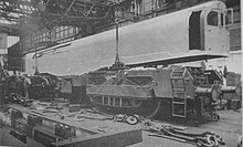
The material was ordered in December 1946 and construction began in July 1947. Although the construction was not yet finished, the production of the frames began in May 1948 at the Brighton Railway Works . Many changes had to be made during the construction of the first locomotive. The two three-cylinder blocks of the steam engine warped during manufacture so that the sleeve valves could not work properly. Despite these setbacks, the first Leader class locomotive was completed in June 1949.
tries
The locomotive was tested from Brighton and there were many problems. As early as November 1949 it was stated that the stoker's workplace had to be changed. The space in the side corridor was too small so that it could not move the coal into the fire box with a normal swing of a shovel. It was also unbearably hot at this point. To fix the problem, changes would have been necessary, which is why work on the four remaining locomotives was discontinued.
It was also shown that the locomotive, in addition to many small defects, was much too heavy and had a considerable unbalanced load. The axle load was 22.2 t instead of 17.2 t, making the locomotive a third heavier than promised. The wheel load on the right side of the locomotive was 9 t heavier than the left, which was over 1.5 t per axle.
Although the project had already devoured £ 176,000 by January 1950, equivalent to around € 6.5 million in 2017, the performance test drives were started. There were high-speed trips, but there were also defects in the sleeve valve control. In addition to steam loss at the valves lubrication caused difficulties, the sleeves so that in the guides firmly ate . The chains for driving the valve control stretched, making control of the steam supply to the cylinders inaccurate. As with the Paget locomotive, the dry fire box with the brick lining did not prove itself. The fireclay bricks cracked, broke and sometimes fell out - an experience that was also made with other fire boxes with brickwork in rail operations.
Some improvements were made during the rides. The mechanism for inclining the valve sleeves has been removed, the play in the axle bearing holder has been increased, and the locomotive has been ballasted in order to equalize the mass of the left side with that of the right. The brick lining of the fire box was improved, which in turn made adjustments to the blowpipe necessary due to the smaller grate area .
The end
The load measurement drives received a bad report on the various defects and the project was abandoned in March 1951, as electrification and the switch to diesel operation were just around the corner. The last run of the only completed locomotive took place on November 2, 1950 in front of a 480 t regular train, which it brought to its destination without delay. After the end of the project, the prototype and the other started locomotives stood around in different depots before they were scrapped.
Bulleid had previously lost interest in the project because he calculated that after the nationalization of the Southern Railway, the successor British Rail would have no interest in such a new type of locomotive. He was also of retirement age and was offered the position of head machine engineer at CIÉ in Ireland , where he built the much more successful peat-fired CC1 based on the Leader class.
technology
The design of Bulleid looked more like an electric or diesel locomotive than a steam locomotive. The closed structure had driver's cabs at both ends, which were connected to one another by a side aisle. Behind the off-center boiler there was a place for the heater in the side aisle, behind which there were the water and coal supplies. It was driven by two three-axle motor bogies .
Engine
Each bogie was powered by a three-cylinder steam engine. As with the Paget locomotive , the cylinders of the direct current steam engine were arranged in a block between the wheels. The steam supply was controlled with sleeve valves that were driven by chains . Not only did the valves move back and forth, but they also tilted 30 ° as they moved, which should avoid difficulties with the earlier similar designs. This device was removed again during the test drives. The cylinders, which were arranged diagonally in front of the front axle, acted on the middle axle of the bogie, the end axles were driven by chains on one side on the outside of the frame.
Steam boiler
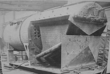
The fully welded boiler was as a normal fire-tube boiler according to Stephenson built, but had a dry firebox . The classic fire box was an elaborate construction made of copper with stud bolts , which was no longer available. Thus, material, production and maintenance costs should be saved. There came a firebox with a lining of refractory bricks on the rear wall and the side walls are used. In contrast to the Brotan kettle , no riser pipes in the area of the fire box were used. The fire box cover was covered with water, and four thermosiphon elements were built into the fire box. The fire hole was off-center to the left on the back wall of the fire box so that it was more easily accessible from the stoker in the side passage.
Web links
- Bulleid "Leader" Class 0-6-6-0T. Southern Railway E-Group, October 16, 2008, accessed October 8, 2018 (3 pages).
Individual evidence
- ^ A b c d Southern Railway E-Group, first page
- ^ A b Southern Railway E-Group, second page
- ↑ a b c d e f g P. Ransome-Wallis: Illustrated Encyclopedia of World Railway Locomotives . Courier Corporation, 2001, ISBN 978-0-486-41247-4 , pp. 463 ( google.com ).
- ^ A b c d Southern Railway E-Group, last page
- ^ The Caretaker's Website: Leader Class Locomotive. YouTube, April 23, 2017, accessed October 11, 2018 (English, from 2:12 am ).


