Steam locomotive boiler

A steam locomotive boiler is a type of steam boiler or a shell boiler for generating steam for the operation of steam locomotives .
construction
Due to the special requirements of mobile use, this design has a number of special design features:
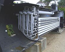
A steam locomotive boiler usually consists , due to the limits of the vehicle gauge , of the rear boiler , the long boiler , which usually consists of several sections, and the smoke chamber attached with a profile ring . While the boiler parts used to be riveted together, modern boilers are completely welded. The steam locomotive boiler is usually a smoke tube boiler.
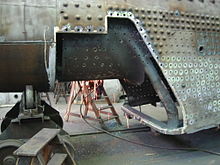
The rear boiler is made up of the standing boiler and the internal fire box . The back boiler and fire box are connected by the bottom ring and together form a water jacket around the fire. The fire box is connected to the outer wall of the boiler with stud bolts and cross anchors . To the front, the rear cup merges into the long cup, usually with a conical transition section. The smoke and heating pipes are installed between the pipe walls in the long boiler. In more modern locomotive boilers, the fire box ends in a combustion chamber that protrudes inside the long boiler.
The smoke chamber tube wall and the profile ring to which the smoke chamber is attached form the front end of the long boiler . The combustion gases collect in the smoke chamber in order to escape into the open via the chimney .
The forces that act on the boiler and fire box walls due to the steam pressure are absorbed by a large number of stud bolts, joint (Skoda) bolts, ceiling and cross anchors that connect these walls. The long boiler is largely stabilized by its cylindrical shape in connection with the internal overpressure. The boiler plates used have a material thickness of 10–20 mm, depending on the boiler pressure.
Steam output
The steam output in Germany is up to 16.6 t / h for old-style boilers ( series 45 boilers ), and up to 22 t / h for new replacement boilers for steam locomotives in Germany (again series 45 boilers ; so-called splinter classes are not taken into account) and in the USA to well over 45 t / h (boilers of various series, e.g. that of the class H-8 of the Chesapeake & Ohio Railway with 672.9 m² evaporation heating surface, 296.1 m² superheater surface and 12.56 m² grate surface, which at is matched to the given heating surfaces for the combustion of hard coal ).
Basically, wet steam is generated in the evaporation process. The superheated steam, which is more economical for locomotive operation , can be extracted using special steam drying or overheating options . For this, superheater elements are built into the flue gas flow. The steam is then dried and superheated in these. The steam temperatures are then, depending on the boiler load, between 300 and 400 ° C. The most common operating pressures for normal pressure steam locomotives are mostly 8 to 16 bar in Germany and 14.1 to 21.8 bar in the USA. Higher operating pressures are possible, but require more complex boiler designs.
Historical building materials and technologies
The development of steam boilers is a story of accidents. The boiler materials were not yet so well developed by metallurgy ; the sheets contained manufacturing defects that could not be found due to the lack of material testing techniques.
At the beginning, copper was mainly used in boiler construction. The metal sheets were connected by rivets . A rivet holds its connection through friction and the molded head. When riveting, a heated piece of metal is inserted into a hole through two metal sheets, compressed from both sides by hammering and a head is formed.
Later steel was used because of its better strength . The steel sheet was also connected by rivets. A little later, fire welding was used to join the steel sheet . The two sheets to be connected were beveled on one side and heated in a fire. The oxide and scale layers were removed with the help of a reducing welding powder. The blacksmiths hit the overlapping shoped surfaces with hammers and welded them in the process. In retrospect, they could not determine how well the connection between the material had turned out. Therefore a certain safety margin had to be given in the overlap.
Modern boiler
Today, new boilers are only welded . The boiler plates must meet a standard. The outer seams of the boiler are subjected to an X-ray or ultrasonic test. The boiler sheets are subjected to a 100 percent ultrasonic test for doubling and voids at the manufacturer. Furthermore, the boiler plate must withstand a tensile test, a notched impact test and a folding test.
Nowadays, the stud bolts are welded into the boiler and fire box wall; in the past they were riveted. The pipes of the long boiler are drawn into the diameter of the fire box pipe wall and welded in, while they are widened and rolled in watertight on the smoke chamber pipe wall . This is to avoid damage from expansion. Recently, pipes have also been welded in on both sides.
The operational steam locomotive boiler expands by 1–5 cm in length, depending on the boiler size. This linear expansion compared to the locomotive frame must be compensated. Therefore, the entire locomotive boiler is only firmly connected to the locomotive frame below the smoke chamber on the smoke chamber support. The rest of the boiler rests on pendulum plates, which can follow the longitudinal expansion. At the end of the fire box, the boiler is secured to the frame with wedges. These are form-fitting, movable clamping pieces that have to be loosened by the boiler operator when heating up or when the boiler is shut down, or which have to be clamped while driving.
The space above the pipes and the fire box is the steam collecting space, which usually ends in one or two steam domes (round boiler structures). Wet steam is taken from the steam domes.
The water room must be constantly filled with water. If the water level sinks below the low water mark, the firebox cover can burn out and crack. The sudden drop in pressure and the ensuing re-evaporation result in very large amounts of steam which, within a very short time, cause the pressure in the standing boiler to rise exorbitantly, which causes the boiler to burst - the boiler pops . In order to prevent the catastrophe at the last moment, it is mandatory to insert one or more melting plugs into the fire box ceiling. The fusible plug is a hollow screw with a Schmelzlotverschluss. If the fire box ceiling heats up too much, the solder melts and the steam jet extinguishes the fire before the ceiling can begin to glow. Replacing the fusible plugs is part of the boiler inspection.
Operational damage
Locomotive steam boilers are subject to various loads during operation that can lead to damage. They are primarily due to the expansion of the material when heated. The boiler material also reacts chemically with the water and the water treatment substances. On the fire side there is abrasion due to oxidation of the boiler plate and pitting due to acidic smoke gases.
- Above all in the smoke and heating pipes as well as the superheater elements, the exhaustion from the flue gases is very strong. After a sufficient operating time, this leads to pitting or longitudinal cracks in the material. For repairs, the affected ends must be cut out and replaced with new pieces of pipe.
- In the fire box, material is consumed directly on the fire box wall and the stud bolts that hold the fire box in the boiler tear. During the boiler overhaul , worn or torn stud bolts, discarded or excessively worn sheet metal pieces are cut out and replaced with new, tested parts. Due to the closed design, the replacement pieces can only be so large that they fit through the ash pan or the fire hole. During operation it can happen again and again that a stud breaks. In order to be able to clearly identify the break, the stud bolts are drilled out from the fire box side at least 60 mm deep. In the event of a break, water from the boiler enters the fire. It is permissible to nail some broken studs. No two stud bolts lying next to each other may be nailed down. Over time, the forces that the stud bolts have to absorb lead to radial cracks that emanate from the stud bolts. The affected sheets must then be replaced.
- In the deep-drawn folds that make up the lower corners between the outer boiler wall and the fire box, material constrictions appear over time. These cannot be welded, the fold must be exchanged.
- At the bottom of the boiler there are chemical reactions between the material and the precipitates of the chemical water treatment. The resulting holes are welded in the next overhaul and sanded flat.
literature
- Leopold Niederstraßer: Guide for the steam locomotive service . Reprint of the 9th edition from 1957, Karlsruhe 1979, ISBN 3-921700-26-4
- Author collective: The steam locomotive . Reprint of the 2nd edition Berlin 1965; Transpress, Berlin 1993, ISBN 3-344-70791-4


