
bogie


A bogie is a running gear of a rail vehicle in which wheel sets are stored in a frame that can be rotated with respect to the car body . Vehicles with bogies, as compared to those with rigidly attached to the vehicle body axes closer sheets pass through, because the frame can unscrew with respect to the car body, and thereby the wheels at a smaller angle to the rail start. In addition, the bogies improve the smoothness of the run, as they only transmit bumps in vertical and transverse directions to the car body in half.
Bogies are built in various designs and designs. In addition to the number of axles, a distinction can also be made between bogies for locomotives , freight and passenger coaches , which place different demands on the design in terms of load capacity , speed and comfort .
construction
Bogies consist of a frame to which all other parts such as wheel sets, suspension and dampers are attached. In the case of powered bogies, the motors and gears are usually also housed in the bogie.
 |
|
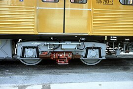
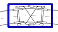
| Parts of a coach bogie | |
|
|
frame
The bogie frame usually consists of two side members running over the axle bearings and one or more cross members. Cross members running in front of or behind the axles are called end supports , bogie frames without rigid end supports are called H frames . They are characterized by the fact that the ends of the H above the axle bearings can twist against each other. Frames without cross members between the axles are sometimes called O-frames . Today, the frame is mostly a welded steel construction, more rarely it also contains cast parts or is cast as a whole. Riveted frames were also used in the past.
- Design

H-frame

O-frame


- processing

cast frame
welded frame

riveted frame


Axle bearing
The axle bearings are used to support the wheelset. They can be arranged to be movable or rigid in the longitudinal direction relative to the bogie frame. Movable axle bearings allow radial adjustment of the axles in arcs under suitable conditions.
The axle bearings are usually located outside of the wheel disks, where they are easily accessible for maintenance, less often between the wheel disks (bogie with internal bearings). In the case of bogies with external bearings, the axle bearings are usually held by axle bearing carriers on which the primary springs and their dampers are attached. For a long time, bogies with internal bearings were common, especially as running bogies for locomotives . Their advantage is to keep the space outside the wheel disks, which is required for rod drives , free. In addition, they are widespread in trams with limited width.
Most European freight car bogies have a wheelbase between 1.8 and 2.3 meters. High-speed vehicles are designed with wheel sets of up to 3 meters to achieve smoother running.

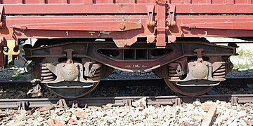
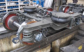
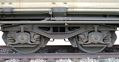
Bogie with external storage

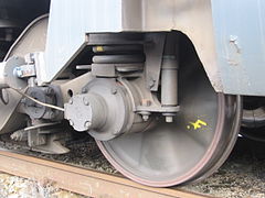
Bogie with internal storage


suspension
The bogies are provided with a suspension for better driving comfort and to be able to drive on twisting of the track, whereby both the axles can be sprung against the bogie (primary suspension) and the bogie frame can be sprung against the car body (secondary suspension). In the case of freight car bogies, usually only one of the spring stages mentioned is implemented, passenger coaches and locomotive bogies usually have both spring stages.
Primary suspension
The axle bearing supports are connected to the bogie frame via the primary springs. Leaf springs were used in the past , now mostly coil springs or rubber layer springs. The axle bearings are guided by axle links that are articulated to the frame.
The coil springs of the primary suspension are usually arranged vertically, except for Wegmann bogies or axle guide bogies. They have triangular journal bearing supports with the journal bearings at the outer corners. The inner corners are rotatably connected to the frame and supported at the upper corners by helical springs lying horizontally on the frame.
Movement of the axle box in the primary suspension

Axle bearing bracket

Axle bearing with axle bearing carrier, two coil springs for the primary suspension and parallel vibration damper
Axle bearing with wishbone and a coil spring for the primary suspension

Axle bearings with Lemniskatenlenker (type Alstom)
Leaf springs on a freight car bogie
Primary suspension with rubber layer springs

Wegmann bogie with horizontal primary springs


Secondary suspension
The secondary suspension in passenger coaches generally consists of helical springs or air springs , in locomotive bogies it consists of helical springs; freight wagons in Europe usually have no secondary suspension .
In the past, the secondary suspension was mostly made with leaf springs. Secondary suspension with Flexicoil coil springs or air springs can also take over the lateral guidance of the bogie and its rotation to the car body, so that the cradle with the lateral sliding pieces is not necessary. If, particularly in the case of motorized bogies, the longitudinal forces are transmitted by pull and push rods, the pivot pin or the pivot socket can also be dispensed with.
Secondary suspension with air springs

Deflected flexicoil springs

Pull and push rod on an ICE1 bogie.


Cradle
In the case of bogies with secondary suspension, the cradle is a cross member that is connected to the bogie frame by springs and that carries the pivot pin. In contrast to cradle-free designs, bogies with cradles can achieve larger turning angles compared to the car body, which is particularly important with tight curve radii.
Bogie with screw-sprung cradle

Bogie with cradle made of leaf springs

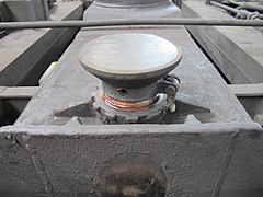
Pivot
The pivot pin, also known as the pivot socket, connects the bogie with the car body and usually also transfers the longitudinal forces between the car body and the bogie. The bogie moves around the vertical axis formed by the pivot. Most of the time, the trolley is also supported on the cradle by sliding plates on the side, but these do not take on any longitudinal or transverse forces. Instead of the pivot, constructions with a lemniscate handlebar can also be used.

Rotary pan on a coach bogie
Sliding plate for lateral support of the car body


Vibration damper
Vibration dampers prevent excessive movements of the parts in the bogie and the bogie between the car body. Leaf springs usually do not require any special vibration dampers, as their movement is already dampened by the friction between the leaves. For the vibration damping of coil or air springs, additional components are usually necessary. Simple friction dampers are used in freight wagons; in vehicles for higher speeds, the primary suspension has to be designed to be very stiff and the turning of the bogie frame in relation to the car body must be hindered with roll dampers in order to achieve a sinusoidal run with the lowest possible frequency.

Roll damper on an ICE3 bogie

Roll damper on a bogie of an ICE-TD ( DB series 605 )


Anti-roll support
In vehicles with a high center of gravity, a roll support can also be installed, which prevents the car body from executing excessive rotary movements around the longitudinal axis. The anti-roll support typically consists of a torsion bar mounted in the bogie to the transverse direction of the vehicle, which is connected to the car body via control arms on both sides. Alternatively, the torsion bar can also be mounted on the car body and connected to the bogie via control arms.

Anti-roll support on a railcar. The arrow points to the center of the torsion bar attached to the car body.

Propulsion equipment

Bogies with driven axles are referred to as motorized bogies (TDG), those without a drive are referred to as running bogies (LDG). In vehicles with electric traction motors , these are usually also accommodated in the bogie, as are the traction gears when power is transmitted via cardan shaft . Motor bogies of vehicles with internal combustion engine drive, which in addition to the drive unit also contain the engine itself, are referred to as machine drive bogies .
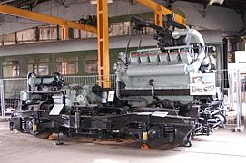
Motorized bogie of a high-speed railcar
Schematic representation of a motor bogie with electric motors:
blue - traction motor,
red - clutch,
pink - pinion,
yellow - large wheel


Because of their different tasks, running bogies and motor bogies have different designs. In addition to their supporting and guiding function, motor bogies also have the task of transmitting power for propulsion. This means that a deep linkage must be implemented in order to distribute the axle loads evenly over the axles. In addition, the bogie frame must be equipped with torque supports on which the forces of the drive are directed into the frame. For the sake of standardization, for example, motor coaches and running bogies are often identical in construction.
Radial control of the wheelsets

In most bogies, the axle box bearings are fixed in the longitudinal direction in the frame, so that the two axles are guided exactly parallel to each other. Depending on the wheelbase, the wheel sets of such bogies can still start to bend considerably.
In some types of bogie, the wheelset bearings are elastically mounted in the longitudinal direction, so that the wheelsets can adjust in arcs radially to the center of the arc. The radial setting is brought about by the equivalent conicity , but can be canceled when driving slowly, when tractive force is transmitted or other disruptive effects, or the wheelsets are even set upside down. If the axle bearings are connected diagonally with cross anchors , it is guaranteed that the axles are at least always in opposite directions. In addition, the radial adjustment of the wheel sets can also be achieved by means of a forced steering mechanism via the turning angle of the bogie frame in relation to the car body, as is used, for example, with Liechty bogies or the SIG Navigator . The radial setting can also be achieved using computer-aided actuators.

axles elastically mounted in the longitudinal direction

Axles connected with cross anchors

axles positively controlled by the car body
Control with actuators


Picture gallery
- Bogies picture pool
Bogie type Y25 in welded construction with wheelsets for an axle load of 22.5 t (most common freight wagon bogie
in Europe)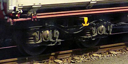
Bogie type TVP 2007 with cross armature controlled, radially adjustable wheel sets for an axle load of 25 t
(derived from type Y25)
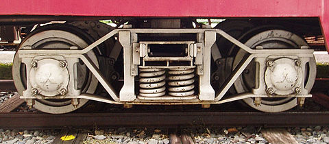
Bogie DB -type 652 with parabolic springs
(of LHB developed and built from 1986)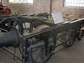
Württemberger bogie in composite construction from 1845
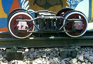
Diamond bogie of an MPSB passenger car around 1890
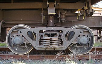
three-piece cast bogie without primary suspension ( Three Piece Bogie ) with lift-off of the axle bearings
(common design for freight cars outside Western Europe)
American freight wagon bogie ( Three Piece Bogie , including type Bettendorf ) with Gleitachslagern


_21.jpg)


- Bogie picture pool imported from en: Bogie

engl. Track = track gauge ( track width minus Micronutrients play);
engl. wheelbase = (bogie) axle base
Bogie of a Euro-car City of SBB , bottom view

American Bierkühlwagen with Diamond bogies
Japanese Diamond bogie with roller axle bearings

three-piece cast bogie without primary suspension ( three piece bogie ), sectional view

American sliding axle bearing, sectional views


Special designs
Multi-axle bogies
Most of the bogies used today are two-axle, but there are also those with three or more axles.
Three-axle bogies are mainly used in locomotives and freight cars for heavy loads. In passenger coaches, they were mainly used in heavy sleeping , dining and saloon coaches so that the permissible axle loads of the route sections traveled were not exceeded. In three-axle bogies, the central axis can usually be shifted laterally to ensure that the sheet travel is free of restraint.
Bogies with up to seven wheel sets have also been built for particularly heavy loads, especially for low-bed wagons . It is no longer a matter of mere drives, but rather fully equipped multi-axle wagons on which a loading bridge is placed. The suspension of neighboring wheel sets are connected to one another with compensation levers so that they are loaded as evenly as possible.

three-axle gooseneck bogie of a passenger coach

four-axle bogie of a low-floor wagon on the rolling road


Single-axle bogies
In rare cases, individual axles were also stored in a frame that could be swiveled out opposite the car body. In order to avoid incorrect settings, single-axle bogies are usually built with a forced linkage that is controlled either by the car body or an adjacent running gear. In the steering three- axle vehicles , a central running axle controlled the deflection of the two driven single-axle bogies at the ends of the wagon.

Single-axle bogie of a diesel railcar

Lenkdreiachslaufgestell a tram rail car.


Bogies with idler wheels
Bogies can also be equipped with idler wheel sets in which the wheel disks can rotate independently of one another. The running behavior of such single wheel bogies or single wheel bogies is different from that of conventional wheelset bogies. Due to the lack of a connection between the two side wheels, there are no slippage forces in the longitudinal direction in the arc, so that there is also no sinusoidal movement in the straight line . However, self-centering in the track is also omitted with idler wheels. Even small deviations from the parallel position of the axles mean that a wheel with the flange on the rail head runs permanently. Unless complex countermeasures are taken, loose wheel sets cause increased wheel flange and rail side wear.
Jacob's bogies
The Jakobs bogie was specially developed for longer, permanently connected freight trains or railcars . Here, two car bodies are supported together on a bogie, with the bogie sitting in the middle between them. With longer train units, the number of bogies is reduced, but the train unit cannot be operationally separated and the axle load increases if the car bodies are the same length. This is often counteracted by the fact that the car bodies are shorter than those of cars with conventional bogies. Also z. For example, on the Tw 6000 tram in Hanover, Jakobs bogies are used between the car parts.
Maximum bogies


In tram railcars in 1900, for example in Munich , Nuremberg , Augsburg , Berlin and Vienna as well as in Filderstadt Railroad Company , found out drive-related reasons Maximum bogies use. The design origins go back to the so-called Maximumtrucks from the JG Brill Company from 1891. The maximum bogies have wheel sets with different wheel diameters. The main load of the car is on the larger, driven wheel set. The smaller wheel set is mainly used for guidance in the track. The higher load on the large drive wheel set by the drive motor and shifted support point means that the “maximum” of power can be transmitted via an axle, and the linkage means that very small arc radii can be negotiated (15 meters in Munich). This made it possible to equip a four-axle railcar with a conventional control system and only two traction motors and still not lose 50 percent of the friction mass for the drive. Maximum railcars could be designed with running axles on the inside, running axles on the outside or with the same axle sequence, but the design with inside running axles was the most widespread. The first maximum railcar in Germany was GBS wagon no. 2080 from 1901. There is no real pivot on maximum bogies; the shape of the sliding pieces means that the pivot point is on the driven axle. The disadvantage is the poorer running properties compared to conventional bogies, since the impacts acting on the driving axles are not halved. In addition, maximum bogies with a leading axle tend to derail due to their low axle load when the track is poor. Due to the further development of control technology and the resulting possibility of using four traction motors in one car with comparable effort, only a few cars with maximum bogies were built after the First World War. The Munich tram was an exception , for which it was procured until the 1930s. Railcars with maximum bogies remained in use well into the second half of the 20th century.
A comparable construction was used again in the 1990s for the short-articulated low-floor railcars GTxN / M / S from AEG and Adtranz . Here, too, a pair of running and driving wheels are arranged in the bogie. As with the Maximum bogie, the support point of the car body is offset towards the pair of driving wheels, so that the driving wheels are loaded with around two thirds of the vehicle mass.
The tram in Brussels also uses asymmetrical bogies in the Tram2000 series, the driving and running wheels of which have different wheel diameters.
See also

literature
- Bogies. In: Viktor von Röll (ed.): Encyclopedia of the Railway System . 2nd Edition. Volume 3: Braunschweigische Eisenbahnen – Eilgut . Urban & Schwarzenberg, Berlin / Vienna 1912, p. 421 ff.
- Karl Gerhard Baur: Bogies - Bogies. EK-Verlag Freiburg 2006, ISBN 3-88255-147-X .
- Ivo Köhler, Uwe Poppel: Maximum bogies - what is that? In: Berliner Verkehrsblätter . No. 8 , 2013, p. 152 f .
- Gerhard Bauer: Tram Archive 1. Transpress-Verlag 1983.
Web links
Individual evidence
- ^ Johannes Feihl: The diesel locomotive - structure, technology, design. Chapter: 6.2 Motor bogies and their linkage. Transpress-Verlag, Stuttgart 1997, ISBN 3-613-71060-9 .
- ↑ Type T (Vienna, 1900–1956) in the Stadtverkehr-Austria-Wiki
- ^ Gerhard Bauer: Tram Archive 1. Transpress-Verlag 1983, p. 179.