
Drum carrier

With the drum hoisting machine , a special rope drum is used as a rope carrier on which the hoisting rope is wound or unwound. Drum hoisting machines are well suited for both particularly shallow and particularly great depths .
history

In the early days of mining , a round tree driven by a crank was used , onto which the hoisting rope was wound or unwound. The Göpel were a further development . Rope drums that had already been further developed were used here. When the hoisting cage was pulled up, the hoisting rope wound itself onto the rope drum in neat turns. The rope was guided through helically running grooves which were located in the wooden covering of the rope drum. From this construction, two-basket conveyors with two conveyor ropes and two drums, one fixed drum and one loose drum, were developed. While drum machines reached their limits in the middle of the 19th century, it is now possible to use modern drum winding machines to convey payloads of 31 tonnes at a speed of 18 m / s from depths of up to 3000 m.
function
A drum winder works on the principle of a rope that is wound onto a drum. When the rope is running down, the rope is unwound from the drum; when the rope is running up, it is wound onto the drum. To ensure frictional engagement, two full windings must remain on the drum when the basket is in the lowest position. For safety reasons, additional rope lengths are usually taken into account when dimensioning the rope length. To prevent the hoisting ropes from loosening from the drum attachment, they must be attached to the rope carrier with at least two rope clamps. The entries are made as slim as possible to ensure that the rope is guided safely onto the drum. A double drum winder is in principle a double reel with one rope wound on each drum and the other unwound.
Weight compensation

During the conveyance, the descending rope becomes longer and therefore heavier. In the case of two-drum conveyors, the rising rope is then shorter and therefore lighter. In the middle of the shaft, both ropes are of the same length and the rope weight is balanced. These different loads lead to a restless and uneven gait of the hoisting machine. This has a disruptive effect on operation. Counterbalancing is achieved in two ways, either through the use of conical rope drums or through the use of counterweights. With the conical rope drums, the hoisting rope is wound onto the spiral drum when the load is pulled up, starting with the smallest drum diameter. With double drum machines, the rope of the descending load is unwound at the same time, starting with the largest drum diameter. The fact that the unwound rope engages the small radius and the wound rope engages the large radius means that the static moments are approximately equal. Due to their size, these drums reach a correspondingly large weight and were only rarely used in Germany. They were used very often in the United States of America and England. In England the drum machines were often provided with counterweights. For this purpose, a second, small cable cage was attached to the cable cage shaft, onto which a counterweight in the form of a chain was wound. This chain was mostly run in a second small shaft, which was next to the conveyor shaft. The weight compensation was achieved by winding and unwinding the chain in opposite directions to the conveying direction. The weight and thus the length of the chain had to be calculated according to the payload.
Designs
Drum hoists are mainly built as floor hoists, due to the strong rope deflection, tower hoists are very rare. A distinction is made between single drum machines and double drum machines (two-drum drive machines). Single drum machines have a drive motor that drives the drum via a gearbox or directly. Drum or disc brakes are used as brakes. Double drum machines are available with a fixed drum and a lottery wheel, as well as with two lottery drums. The loose drums are connected to the drive shaft as cable carriers via a hiding device. The drive takes place here by one or two motors. The motors can be coupled directly or connected to the drum via gears. Drum or disc brakes are also used here as brakes. In the case of two-drum machines, it is possible to equip them with a so-called hiding device. With these machines it is imperative that a separate brake is available for the lottery wheel to hide it.

Drum winder with steam drive

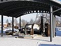
Drum carrier at the Soudan Mine

Side view of the carrier

Drum conveyor with a cylindrical drum
Drum winder on the grounds of the Oelsnitz Mining Museum
.jpg)


Two-basket operation
In some mines, e.g. B. in ore mining, it is often necessary that several different levels must be conveyed during one shift. In the case of drum hoisting machines with a double drum, two-cage operation is possible from each sole . For this, the drums must be equipped with lottery drums. These loose drums can be coupled in any position of the fixed drum. In order to operate the two- basket operation from a midsole, a conveyor basket must first be positioned on the corresponding midsole. Then the lottery wheel on the respective side is blocked and uncoupled with a parking brake. As a result, the drum does not rotate when the second conveyor cage is positioned. After the second basket has been positioned at the appropriate point, the loose drum on the first side is coupled again with the fixed drum and the parking brake is released.
Great depths

Normal drum winding machines reach their limits at great depths. This is due to the large dead weight of the hoisting rope, which, in addition to the weight of the payload and the weight of the conveyor, must also bear its own weight. In 1957, engineer Robert Blair presented a drum hoist in which the cable carrier was designed for two hoist ropes. Due to its special construction, this system is suitable for particularly great depths (> 2300 meters). In 1958 the first Blair hoist was installed. The cable drum on this machine has two winding areas. The hoisting rope is a continuous rope that is attached to both drums. The hoisting rope is not attached to the bucket with an intermediate harness, but is guided around a deflecting disk attached to the bucket . Load balancing is achieved using a second, identical system. The two systems are coupled either electrically or mechanically . If the two systems are electrically coupled, the system reacts like two separate machines. With the mechanical coupling, the two systems are connected to one another via a cardan joint. In this way, the compensating force of the other strand is used and the required torque in the loaded system is reduced. Blair carriers are mainly used in South Africa.
Examples of drum carriers
A Blair single drum hoisting machine was in operation at the Ibbenbüren mine . The machine carried a maximum payload of 15 tons from a depth of 1500 meters. The machine had a direct drive with a drive power of 1500 kilowatts . At the Kidd Creek mine there is a double-drum hoisting machine with a drive power of 4,000 kilowatts. The machine is equipped with hiding devices and can move a payload of 16.8 tonnes from a depth of 1818 meters at a conveyor speed of 16 meters per second. The drum diameter of the rope carrier is 5.5 meters. At the former Ramsbeck ore mine there is the largest drum winder that has ever been installed underground in Europe. The machine served as a drive for a blind shaft and had a drive power of around 1250 kilowatts. A double-drum hoisting machine with a drive power of 2,450 kilowatts is operated at the Neves Corvo mine. The machine is equipped with a hiding device and can lift a payload of 12.5 tons from a depth of 585 meters with a conveying speed of 12.5 meters. The diameter of the cable carrier is 6.1 meters.
Individual evidence
- ↑ a b Technical requirements for shaft and inclined conveyor systems (TAS) page 11/6 Definitions . Online (accessed August 4, 2016)
- ↑ a b c d Siemag Tecberg drum conveying machine examples.
- ↑ Wolfgang Weber: Hemp conveyor ropes in the 18th - 19th centuries, manufacture and strengths . Online ( Memento from December 12, 2013 in the Internet Archive ) (PDF; 4.7 MB) In: Bergknappe 90. 4/1999, pp. 19–23. (accessed June 10, 2011).
- ^ Wilhelm Leo: Textbook of mining science. Printed and published by G. Basse, Quedlinburg 1861.
- ^ Franz Rziha: Textbook of the entire art of tunneling. First volume, published by Ernst & Korn, Berlin 1867.
- ^ LWL Industriemuseum: The Koepe Funding (accessed on June 10, 2011).
- ↑ C. CH. Böttcher: Bernoulli's steam engine theory. Fifth edition, Verlag der JG Cotta'schen Buchhandlung, Stuttgart 1865.
- ↑ Technical requirements for shaft and inclined conveyor systems (TAS) section 3.3.10. + 3.3.11. Rope carrier .
- ^ J. Niederist: Fundamentals of mining science. kk court book and art dealer FA Credner, Prague 1863.
- ↑ a b c d H. Hoffmann, C. Hoffmann: Textbook of mining machines (power and work machines). 3. Edition. Springer, Berlin 1941.
- ^ A b Emil Stöhr, Emil Treptow: Basics of mining science including processing. Spielhagen & Schurich publishing house, Vienna 1892.
- ↑ a b Journal for the mining, metallurgy and saltworks in the Prussian state. Ninth volume, published by the royal secret upper-court book printing company, Berlin 1861.
- ↑ Technical requirements for shaft and inclined conveyor systems (TAS) section 3.3.9. Rope carrier.
- ^ Carl Hellmut Fritzsche: Textbook of mining science. First volume, 10th edition. Springer Verlag, Berlin / Göttingen / Heidelberg 1961.
- ^ A b c Howard L. Hartman, Jan M. Mutmansky: Introductory mining engineering. Wiley-Interscience Publication, 1987, ISBN 0-471-82004-0 .
- ↑ Alfred Carbogno: Mine hoisting in deep shafts in the first half of the 21st Century. Online (accessed June 14, 2011; PDF; 305 kB).
- ↑ Siemag TECBERG: Technical Information, Blair double drum hoist for South Deep Gold Mines (South Africa). Online (accessed June 14, 2011; PDF; 756 kB).
- ↑ The largest underground drum winder in Europe ( Memento from January 3, 2009 in the Internet Archive ) (accessed June 10, 2011).
See also
- Traction sheave , or Koepe sheave