Wind tunnel
A wind tunnel is used to examine and measure the aerodynamic and aeroacoustic properties of objects.
The best known are probably the wind tunnel examinations of airplanes and cars . Investigations in the wind tunnel are used to investigate air resistance , dynamic lift or deformations due to aeroelasticity .
Models of structures such as high-rise buildings , chimneys and bridges are also examined in wind tunnels. With them, the aim is to assess whether they can withstand the expected wind forces in their original size during storms. In order to be able to simulate the wind flow correctly, the entire immediate environment sometimes has to be modeled. Only a few objects can be meaningfully examined in the wind tunnel without scaling. Cars are an exception because they are not too big and the relatively low air speeds allow sufficiently large wind tunnels. Scale models are used for aircraft or buildings . The shape of the flow around a body depends on its Reynolds number . In order to obtain realistic results, the investigation in the wind tunnel must be carried out with the same Reynolds number as it corresponds to the flow around the original. This can be achieved through a higher density of the medium or through a higher speed.
construction

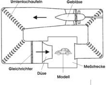
Wind tunnels consist of one or more fans that generate the air flow, rectifier elements that are intended to ensure the most uniform, non-turbulent flow possible, a nozzle to accelerate the air flow and the actual measuring section in which the investigations are carried out. The flow in the measuring section should be as uniform, parallel, and low in turbulence and noise as possible. The degree of turbulence in the wind tunnel provides a quantitative statement about the turbulent fluctuation speeds. As shown in the graphic, the measuring section can be open, i.e. In other words, the flow is blown out from the nozzle into a measuring hall and collected on the other side of the measuring hall by a collector or collector, with a shear layer building up between the moving and standing air in the measuring hall. However, there are also closed measuring sections in which the flow is also guided through walls in the measuring section, and slotted measuring sections in which some of these walls are provided with slits.
The air duct of wind tunnels can also be open or closed. With the open design, the air is sucked in from the environment, flows through the measuring section and escapes back into the open at the other end. Closed air ducts are ring-shaped. Here the air flow picked up by the collector after the measuring section is fed back to the fan . Low temperatures and high pressure can only be generated in closed wind tunnels ( climatic wind tunnel ). Wind tunnels for subsonic speeds can have a diameter of several meters, but the size of wind tunnels for the high supersonic range shrinks to a few centimeters.
Wind tunnel experiments are always associated with high costs, mainly because of the high investment costs involved in creating them. Therefore, attempts are increasingly being made today to replace the experiments with numerical flow simulation (CFD, computational fluid dynamics ). The phenomena are already represented quite well today. In reality, however, the vision of replacing wind tunnel experiments with numerical simulation is still a long way off. This is all the more true for aeroacoustic simulation (CAA, Computational Aeroacoustics ).
Wind tunnels can be classified according to their mode of operation as follows:
Fan driven wind tunnels
- Open channel or Eiffel channel : draws in test gas from the atmosphere and blows it out again.
- Closed channel or Göttingen channel : returns the test gas in a closed circuit. Allows the operating pressure and temperature to be varied
- Cryochannel
Storage wind tunnels (intermittent operation)
- Pressure accumulator wind tunnel: test gas flows from a pressure vessel to the wind tunnel measuring section. Pressure and temperature control of the test gas required.
- Vacuum storage wind tunnel: test gas is sucked from the atmosphere into the vacuum storage. No pressure and temperature control required.
Wind tunnels operated with unsteady pressure waves
Basic principle: A high pressure storage pipe is separated from the low pressure pipe by a bursting membrane. When the membrane bursts, unsteady pressure waves arise. An unsteady shock wave runs into the low-pressure pipe with a wake flow in the same direction. At the same time, an unsteady expansion wave runs into the high-pressure pipe, which induces a flow in the opposite direction to the direction of travel of the wave. The currents induced in this way are used in various types of test facilities.
- Shock tube or shock tube : uses wake flow of the unsteady shock wave. Measurement times in the millisecond range. Variants: Shock wave channel: post-acceleration of the test gas with a supersonic nozzle.
- Pipe wind tunnel or Ludwieg pipe : the test gas is pre-accelerated by an unsteady expansion wave and post- accelerated by a wind tunnel nozzle. The expansion wave runs through the storage tube, which can be designed in great length, in both directions, so that measurement times in the range of seconds can be achieved.
Historical

Eiffel Canal
In 1905 and 1906 Gustave Eiffel carried out investigations on the flow resistance of rectangular and oval plates on the Eiffel Tower by letting them fall vertically downwards on a wire rope from the second platform of the tower. The force acting on the plate was recorded on a metal cylinder wrapped with sooty paper. In 1909 Gustave Eiffel built a laboratory with a wind tunnel on the Champ de Mars , which was moved to Auteuil in 1912 . The Laboratoire Aerodynamique Eiffel can still be visited there today. The wind tunnel consisted of a closed measuring cabin, from which the air was sucked out on one side with the help of an electric fan (the “70 HP” electricity for this was supplied by the power center of the Eiffel Tower). On the opposite side of the room, air flowed from a large storage room through a nozzle into the inside of the measuring section. In the air jet generated in this way, Eiffels employees later also carried out systematic investigations into the behavior of the first wing shapes for aircraft. This type of open channel, which is fed by outside air, is therefore also called the “Eiffel Canal”. An Eiffel canal has the disadvantage that temperature and pressure fluctuations as well as speed differences from the environment from which the air is sucked in continue into the measuring section, so that the flow can only be kept and adjusted laminar within certain limits.
Göttingen Canal

For this reason, among other things, Ludwig Prandtl developed a different form of the wind tunnel and implemented it for the first time in 1908 in the model research institute for aerodynamics he founded in Göttingen . In a wind tunnel of the Göttingen type, the air behind the measuring section is sucked off by a fan in a collecting funnel, from where it flows back to the nozzle in front of the measuring section via a duct. In this way, the physical properties of the air in the duct can be well controlled. You can z. B. bring the entire channel and the measuring section under increased pressure or cool. There are channels in which pressures up to 120 bar or temperatures down to −200 ° C are used. As a rule, a Göttingen-type duct is also more efficient , since the kinetic energy of the air flowing out of the measuring section is reused. Therefore, most wind tunnels with high power / jet speed have a closed circuit.
This construction method was inspired by an experimental channel that Prandtl used in Hanover to carry out investigations with flowing water. Instead of the fan, a water wheel was set in rotation by means of a hand crank in this approximately 2 m long and 20 cm wide canal, whereupon the water in the measuring section was sucked off and through a flow duct located below it back to the other side of the measuring section streamed. Obstacles could be inserted into the open channel from above and the flow around them could be observed.
See also
- Aeroacoustic wind tunnel
- DNW - German-Dutch Wind Tunnels , Marknesse (NL)
- European transonic wind tunnel
- Henrich Fockes wind tunnel in Bremen
- Hypersonic wind tunnel
- Climatic wind tunnel
- Rail Tec Arsenal , operator of the climatic wind tunnel in Vienna
- Flow measurement technology
- Spin tower
- Supersonic wind tunnel
- Vertical wind tunnel
- Water channel
literature
- Theo Hottner: A century of wind tunnel technology. Balance sheet and perspective . GRIN Verlag, Munich 2019, ISBN 978-3-346-00574-8 .
Web links
- Institute for Aerodynamics and Gas Dynamics at the University of Stuttgart - test facilities
- Institute for Aerospace at TU Berlin - flow channels
- NASA Kids Science News Video - Wind Tunnels (English)
- DNW, German-Dutch Wind Tunnels (English)
- FKFS - Research Institute for Automotive and Vehicle Engines Stuttgart
- Theodore von Kármán Wind Tunnel Laboratory , Budapest University of Technology (BME), Hungary
- Wind tunnel that can be remotely controlled via the Internet to determine the c W value of model cars (multilingual, see "RCLs")
- Wind Tunnel Experiments for Grades 8–12 (English)
- Climatic wind tunnel in Vienna
- Wind tunnel simulator planet-schule.de SWR
Notes and evidence
- ↑ Laboratoire aérodynamique Eiffel , 67 Rue Boileau, XVI. Arrondissement, Paris
- ↑ Aérodynamique Eiffel et sa soufflerie
- ↑ DNW - German Dutch Wind Tunnels


