XLR
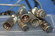
XLR (also called Cannon plug after James H. Cannon, founder of Cannon Electric Co.) is an industry standard for electrical plug connections. In professional sound reinforcement and recording studio technology, XLR connectors are used for analog microphone and loudspeaker signals as well as digital AES / EBU audio signals and DMX control signals . They are available from several manufacturers and their mechanics and dimensions are standardized in the international standard IEC 61076-2-103 . The uniform contact assignment for the audio technology sector is specified in the AES-14 specification of the Audio Engineering Society .
Executions
XLR connectors are available in three to seven-pin versions and in various protection classes according to VDE .
The three-pin XLR connector is the standard connection for analog audio lines in professional sound engineering, especially with symmetrical signal transmission . It is also popular for loudspeaker cables, but is increasingly being replaced by the Speakon system. It only transmits a mono signal ; Two three-pin XLR connectors are required to transmit both channels of a stereo signal.
The norm for the transmission of DMX control signals provides for the five-pin XLR connector as standard; Frequently (especially with cheaper devices), however, three-pin connectors are also used here, which also offer the advantage of being able to be extended with microphone cables if necessary (provided that these correspond to the electrical specifications of the DMX interface).
Five-pin XLR connectors are also used in professional sound engineering, for example, to transmit stereo signals symmetrically and only have to lay one line:
- 1 - mass
- 2 - signal 1+
- 3 - signal 1−
- 4 - signal 2+
- 5 - signal 2−
Four-pole XLR connectors are used, for example, to supply power to video cameras and their accessories, as well as to connect intercom- receiver-speech combinations. In the three- (at Shure under the name TRQ ) or four-pole mini version, they are also used in pocket transmitters for wireless microphone systems. Mini-XLR connectors are also used in professional audio equipment (including portable digital recorders, radio receivers, etc.). The assignment is the same as for the standard XLR connector:
- 1 - mass
- 2 - signal +
- 3 - signal -
Occupancy
| application | Pin 1 | Pin 2 | Pin 3 |
|---|---|---|---|
| symmetrical | Screen / ground | Signal + | Signal - |
| asymmetrical | Screen / ground | signal | bridged to pin 1 |
| Loudspeaker line | Signal - | Signal + | unoccupied (open) |
| Digital line according to AES / EBU |
Screen / ground | Signal + | Signal - |
| DMX -Leitung | Screen / ground | Signal - | Signal + |
| voltage supply |
Dimensions | +12 V | unoccupied (open) data control line |
| Assignment Mini XLR |
Pin code | guitar | Condenser microphone |
|---|---|---|---|
| 1 | Dimensions | Dimensions | |
| 2 | free | Dimensions | |
| 3 | Audio | Audio | |
| 4th | free | Bias |
The pin designations 1, 2, 3 are stamped into the plastic holder. There is also a guide lug at pin 2.
In German, connectors with protruding contact pins are called plugs and those with corresponding “holes” are called sockets . In XLR connectors people speak of "male" (English. Male ) and "female" (English. Female ) connectors and installation versions referred to both sexes as "jacks". Standard XLR connection cables have a male and a female end and can therefore be strung together without additional connecting elements.
With XLR, the typical microphone input on the mixer is female and a microphone has a male connector on the housing as output. One of the reasons for this is the phantom power, which can be used to supply upstream devices with power. The phantom power works with voltages of up to 48 volts and is protected against contact and short circuits by the female design of the connector. A short circuit in the phantom power supply would briefly cause severe overload at the signal input .
Outputs are male for speaker connections too . The use of XLR connections is prohibited for amplifier outputs of more than 100 watts, because dangerous voltages may be present there (the pins of the male XLR connector are inside the connector housing, but can be touched with a fingertip). In the professional sector, only Speakon and screw connections can be found here.
In the case of DMX control lines, the signaling connectors are female in order to avoid short circuits caused by foreign objects.
Exceptions to the current symmetrical standard assignment for audio devices (Pin 1: GND, Pin 2: Plus, Pin 3: Minus, see table) can be made with some older audio devices (e.g. BSS DPR 402/502, Klark Teknik DN500 / 504/510 in the factory configuration, widespread analog devices for automatic dynamic control) occur where pins 2 and 3 are swapped. Pin 3 then carries the plus signal, pin 2 the minus signal, pin 1 carries the shield as with the standard assignment.
Designs
There are many different versions of the XLR built-in connectors. Due to the popularity of the manufacturer Neutrik in this market segment, the type designations of this manufacturer represent the de facto standard for the designations. With the now common D design , the housing openings for male and female connectors are the same, which is a factor in the manufacture of prepared mounting plates big advantage is. In the older P-type , the male version has mounting holes directly above and below the connector opening to save space; the female version looks similar to the D design, but is slightly raised. There are other series with other, sometimes more compact, hole patterns, which mainly play a role in the series production of devices and often enable a simpler construction as well as easier mechanical integration and higher packing densities.
Meaning and origin of the designation
The XLR connector was originally developed by the US company Cannon (now part of ITT ). For use as a microphone connector, the then relatively small circular connectors of the Cannon-X series were provided with a snap lock and sold as Cannon-XL (L = Latch). Later at Cannon the female connectors were filled with a resilient polychloroprene mixture and designated as Cannon XLR (R = Resilient). This connector became so popular that it was even called the Cannon plug , and the replicas took on the XLR designation, although they actually copied the XLR connectors, not the XLR connectors.
Use as a balanced audio connection was specified in the US standard EIA RS-297-A.
In English usage there is the following rule of thumb for the assignment of the pins, which is based on the letters:
- 1 - e X ternal (German: "outside") or also X creen (for screen) = German: "shielding" for ground
- 2 - L ive or L ine (signal = hot)
- 3 - R eturn (return line = cold)
This motto reads in casual German: "ni X - L eiter - R ück (or also: R eturn)"; where “nix” (coll. for “nothing”) stands for the ground on which no signal is sent and its return does not take place either. The other names are self-explanatory.
The forerunner of the XLR connector in European audio technology was the Tuchel connector , which is available in two very different versions, the smaller of which (Kleintuchel) differs from the DIN audio connections for home use only in that it is more robust and has a screw lock. The pin assignment of XLR and DIN connectors differ, however.
Advantages of XLR compared to jack connections
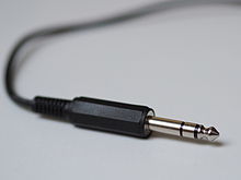
- During the process of plugging a jack plug , the signal wires are usually briefly connected to the signal ground when they are inserted into the socket and thus inadvertently short-circuited. In addition, the open design can cause interference when lying around due to contact with foreign metal parts. XLR connectors do not show this danger either when plugged in or when lying around.
- The contact socket 1 of the female XLR connector is a leading contact a little further forward than contacts 2 and 3. When plugging in, the ground connection is established first. This avoids harmful high voltage peaks.
- XLR connectors are lockable, lockable jack sockets are rare and less reliable.
- The contact surfaces of the XLR connector are far less dirty because they are surrounded by the housing and do not come into contact with other objects or skin surfaces.
- The metal XLR connector housing is generally not connected to ground, but only designed as a Faraday cage without reference to ground or cable shielding. This rules out the possibility of a voltage introduced by contact leading to interference. This separation does not exist with the jack plug shielded with a metal housing.
- The pins of the XLR connection are surrounded by the contact sockets like pliers. In the case of jack connections, on the other hand, the sliding tongues of the socket to the surface of the round plug only create a point connection. This contact surface is much less favorable than with XLR connections, and the contact pressures are higher with XLR. This reduces the contact resistance .
Web links
Individual evidence
- ↑ Connectors for electronic equipment - Part 2-103 : Circular connectors - Detail specification for a range of multipole connectors (type 'XLR') , engl.
- ↑ AES Standard AES14-1992 (r2009) : AES standard for professional audio equipment - Application of connectors, part 1, XLR-type polarity and gender, engl.


