Yagi-Uda antenna
A Yagi-Uda antenna (common name also Yagi antenna ) is a directional antenna for receiving or transmitting electromagnetic waves in the range from around 10 MHz to around 2500 MHz. It consists of a fed dipole , a number of directors in front of and usually a reflector behind the dipole.
history

The Yagi-Uda antenna was developed from 1924 by the Japanese Hidetsugu Yagi and Shintaro Uda . In 1926 they published the first description in a Japanese magazine. In June 1928 an English article by Yagi was published in the USA, so that the antenna in the German-speaking area usually only bore Hidetsugu Yagi's name. While the Japanese patent lists both inventors, the basic patents for other countries only name Yagi as the inventor. The correct name Yagi-Uda antenna is rarely used. In 1930 a device with a Yagi-Uda antenna, which enabled connections over 20 km at a wavelength of 45 cm, was shown at a world exhibition in Belgium. During the Second World War, Yagi antennas, some with parabolic mirrors , were used for radar . The design was quickly put to commercial use in Europe and North America and also spread to amateur radio because of its self-construction method with good antenna gain. In the early 1950s, the design became popular for TV broadcasters on the edge of the reception area.
construction

A characteristic of the Yagi-Uda antenna is a dipole which is given a directional effect by at least one or a series of appropriately arranged directors and possibly reflectors.
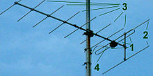
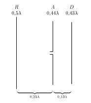
The dipole (1), designed as a folded dipole in the picture on the right , is fed via the supply line (4). The dipole has a length of almost half a wavelength (λ / 2) of the radio waves to be received . Because of its thickness, it is somewhat smaller than λ / 2 in a vacuum. The directors (3) are a little shorter, the reflectors (2) a little longer than the dipole. Dipole, reflector and directors are not electrically connected, but only coupled via the electromagnetic field. However, they can be mounted in the middle of the elements on a common conductive support rod because voltage nodes are located there. The distance between the reflector (s) and the dipole is, for example, approximately 0.15 λ, and between the dipole and the first director, for example, 0.1 λ; In doing so, the profit can be improved at the expense of the bandwidth or vice versa by a suitable choice of element length and spacing. About the first director and the dipole together form the radiation center, so the reflector spacing is less than a quarter wavelength.
properties
The total length of the antenna determines the gain and directivity. The suitable choice of the parameters length , distance , diameter and number of directors optimizes the antenna properties.
A three-element Yagi-Uda antenna 0.3 λ in length provides an antenna gain of 4–8 dBd . With a length of 4 λ (15–30 directors) it amplifies with approx. 15 dBi and reaches an opening angle of less than 40 °.
With individual antennas for the UHF range, around 18 dBi are achieved.
The practical upper limit for the antenna gain is 20 dBi. By interconnecting several individual antennas to form an antenna group , usually up to 4, the resulting antenna gain can be increased even further.
Working method
The active dipole excites the parasitic elements , i.e. the reflector and the directors. The parasitic elements also act as radiators, but they radiate out of phase with the active dipole. The ( resonant ) length deviating from the dipole results in inductive or capacitive behavior with corresponding phase shifts of the currents in the elements. The phase shift is determined not only by the transit time to the element position on the side member (the so-called boom ), but also by the length of the element. The vibration of the exciter is passed on from director to director. The delay from director to director is represented as the phase velocity , which, depending on the ratio of the geometric antenna length to the wavelength, reaches about 0.7 to 0.98 times the speed of light.
The far field of the Yagi ultimately arises from the direction-dependent and phase-dependent superposition of the radiation components of all elements of the Yagi-Uda antenna. In the direction of the boom (forwards), the field components are constructively superimposed (supplementary), to the right and left of this, on the other hand, the superposition is quickly destructive (extinguishing) with increasing angle, which results in the preferred direction.
In the relevant specialist literature there are various details for an "optimal design", each suggesting different gradations of the element lengths and distances. Experiments have shown that small, continuous variations in length and distance lead to higher gains than simply adding "short" antennas with additional elements of the same length and spacing. This was attributed to the consideration of the Yagi-Uda as a "waveguide structure" on which a traveling wave (starting from the fed dipole element) propagates towards the tip of the antenna. According to theory, the element variation should create an improved transition to the free space here.
operation area
Antenna array of six Yagi-Uda antennas with crossed dipole (2 m / 137 MHz) for communication with satellites.
Yagi-Uda antennas can also be used at very high frequencies, for example for receiving Meteosat (1690 MHz ). Antennas with up to 30 elements and antenna gains of up to 16 dBd are used there. In 2020, physicists from the University of Würzburg even presented a Yagi-Uda antenna with a length of less than a micrometer for emitting light waves. Above about 2 GHz, however, the desired radiation properties can be better achieved with other antenna types, for example horn radiators .
Radio amateurs often use rotatable Yagi-Uda antennas made up of three or more elements in the wave ranges from 0.1 m to 40 m (3 GHz to 7.5 MHz). Yagi-Uda antennas for longer wavelengths are rare because the elements then become very large and heavy. In addition, because of the ground effect, such antennas require an installation height of at least half a wavelength. In addition, alternative designs such as the Hexbeam are used.
Yagi antennas are also sometimes used in shortwave broadcasting.
literature
- Eberhard Spindler: The great antenna book. 11th edition. Franzis-Verlag, Munich 1987, ISBN 3-7723-8761-6
- Alois Krischke: Rothammels Antennenbuch. 11th edition. Franckh Kosmos Verlag, Stuttgart 1995, ISBN 3-440-07018-2
Web links
- Explanation of the function of elements of a Yagi antenna radartutorial.eu
- Photos of yagi antennas on analog television
Individual evidence
- ↑ H. Yagi: Beam Transmission of Ultra Short Waves . In: Proceedings of the IRE . tape 16 , no. 6 June 1928, p. 715-740 ( ieee.org [accessed April 13, 2010]).
- ^ The true story of Yagi Antenna. In: The DX Zone. November 25, 2014, accessed May 9, 2020 .
- ↑ 特許 第 69115 号 , Patent DE475293 . , Patent FR619932 . , Patent GB263753 . , Patent GB263752 . , Patent US1745342 . , Patent US1860123 .
- ↑ 八 木 ・ 宇田 ア ン テ ナ. Research Institute of Electrical Communication, Tohoku University , accessed May 9, 2020 (Japanese).
- ^ Roger I. Wilkinson: Short Survey of Japanese Radar — I. (PDF; 1.2 MB) In: Electrical Engineering, Vol. 65 (Aug.-Sept. 1946). 1946, p. 374 , accessed on May 9, 2020 (English).
- ↑ Birth of Radio Astronomy (Ⅷ). In: The History of Amateur Radio. Retrieved May 9, 2020 .
- ↑ Harold Harris: http://rfcafe.com/references/radio-news/yagi-antenna-radio-television-news-october-1951.htm. In: Radio & Television News. Ziff-Davis, October 1951, accessed May 9, 2020 .
- ^ W. Walkinshaw: Theoretical treatment of short Yagi aerials . In: Electrical Journal of the Institution of Engineers - Part IIIA: Radiolocation . tape 93 , no. 3 , 1946, pp. 598-614 .
- ↑ Johannes Endres : The 0 euro antenna. Build your own WiFi antenna from waste. Heise Zeitschriften Verlag, September 26, 2008, accessed on July 9, 2020 .
- ↑ Nano antennas for data transfer. Press release. University of Würzburg, January 8, 2020, accessed on May 9, 2020 .
- ↑ Tower 7 (M7) Radio Arcala Mammoth 160 / 80M Beam in a Nutshell. Radio Arcala, accessed December 28, 2014 .


