
Color Graphics Adapter
This article needs additional citations for verification. (December 2007) |

The Color Graphics Adapter (CGA), originally also called the Color/Graphics Adapter or IBM Color/Graphics Monitor Adapter,[1] introduced in 1981, was IBM's first color graphics card, and the first color computer display standard for the IBM PC.
The standard IBM CGA graphics card is equipped with 16 kilobytes of video memory, and can be connected either to a NTSC-compatible monitor or TV via an RCA jack, or to a dedicated RGBI interface CRT monitor, such as the IBM 5153 color display.
Built around the Motorola MC6845 display controller, the CGA card features several graphics and text modes. The highest resolution of any mode is 640×200, and the highest color depth supported is 4-bit (16 colors).
Color palette
Despite varying bit depths in graphics mode (see below), colors internally are always processed with four bits, yielding 2^4 = 16 different colors. The four color bits are arranged according to the RGBI color model: The lower three bits represent red, green and blue color components; a fourth "intensifier" bit increases the brightness of all three red, green and blue components.
| Full CGA 16-color palette | |||
|---|---|---|---|
| 0 | black #000000 |
8 | (dark) gray #555555 |
| 1 | blue #0000AA |
9 | bright blue #5555FF |
| 2 | green #00AA00 |
10 | bright green #55FF55 |
| 3 | cyan #00AAAA |
11 | bright cyan #55FFFF |
| 4 | red #AA0000 |
12 | bright red #FF5555 |
| 5 | magenta #AA00AA |
13 | bright magenta #FF55FF |
| 6 | brown #AA5500 |
14 | yellow #FFFF55 |
| 7 | white (light gray) #AAAAAA |
15 | bright white #FFFFFF |
With an RGBI monitor
These four bits are passed on unmodified to the DE-9 connector at the back of the card, leaving all color processing to the RGBI monitor connected to it. With respect to the RGBI color model described above, the monitor would use approximately the following formula to process the digital four-bit color number to analogue voltages ranging from 0.0 to 1.0:
red   = 2/3*(colorNumber & 4) + 1/3*(colorNumber & 8);
green = 2/3*(colorNumber & 2) + 1/3*(colorNumber & 8);
blue  = 2/3*(colorNumber & 1) + 1/3*(colorNumber & 8);
| Dark Yellow | |
|---|---|
| 6 | #AAAA00 |
This will result in colors as reproduced on the right-hand side, with the exception of color 6: when using the formula above, color 6 would become dark yellow, as seen to the left. In order to achieve a more pleasing brown tone, special circuitry in most RGBI monitors, including the IBM 5153 color display[2], makes an exception for color 6 and changes its hue from dark yellow to brown by halving the analogue green signal's amplitude:
if (colorNumber == 6) green = green / 2;
It is this "RGBI with tweaked brown" palette, shown to the right, that all later PC graphics standards such as EGA and VGA have retained for compatibility.
With a composite color monitor/television set
For the composite output, these four-bit color numbers are encoded by the CGA's onboard hardware into an NTSC-compatible signal fed to the card's RCA output jack. For cost reasons, this is not done using an RGB-to-YIQ converter as called for by the NTSC standard, but by a series of flip-flops and delay lines[3][4]. Consequently, the hues seen are lacking in purity; notably, both cyan and yellow have a greenish tint, and color 6 again looks dark yellow instead of brown:

RGBI Monitor availability
When the CGA was introduced in 1981, IBM did not offer an RGBI monitor of their own[5], instead, customers were supposed to use the RCA output with a user-supplied RF modulator to connect it to their television set[6]; the IBM 5153 color display would not be introduced until 1983. Resulting from the lack of available RGBI monitors in 1981 and 1982, many users would use simpler RGB monitors (without provisions for the 'intensifier' bit), reducing the number of available colors to eight, and displaying both colors 6 and 14 as yellow[5]. This is relevant insofar as if an application or game programmer used either one of these configurations, he will have expected color 6 to look yellow instead of brown.
Standard text modes
CGA offers two text modes:
- 40×25 characters in up to 16 colors. Each character is a pattern of 8×8 dots. The effective screen resolution in this mode is 320×200 pixels (a pixel aspect ratio of 1:1.2), though individual pixels cannot be addressed independently. The choice of patterns for any location is thus limited to one of the 256 available characters, the patterns for which are stored in a ROM chip on the card itself. The display font in text mode (the code page 437 character set) is therefore fixed and cannot be changed (although when using the original IBM CGA in an original IBM PC, it is possible to select one of two different fonts—normal or thin—by changing a jumper. Many clones didn't offer this possibility). The card has sufficient video RAM for 8 different text pages in this mode.
- 80×25 characters in up to 16 colors. Each character is again an 8×8 dot pattern (the same character set is used as for 40×25), in a pixel aspect ratio of 1:2.4. The effective screen resolution of this mode is 640×200 pixels. Again, the pixels cannot be individually addressed. Since there are twice as many characters on the screen in this mode, the card has enough video RAM for just 4 different text pages.
In every text mode, each character has a background and a foreground color — e.g. red on yellow text for one character, white on black for the next, etc. While the same 4-bit nybble used for the foreground color would normally allow all 16 colors to be used for the background color, the most significant bit of the background nybble is also used to denote whether or not the character should blink (a hardware effect offered by CGA independent of the CPU). The blinking attribute effect is enabled by default, so disabling it is the only way to freely choose the latter 8 color indexes (8-15) for the background color.
Standard graphics modes
CGA offers two commonly-used graphics modes:
- 320×200 pixels, as with the 40×25 text mode. In the graphics mode, however, each pixel can be addressed independently. The tradeoff is that only 4 colors can be displayed at a time. However, only one of the four colors can be freely chosen from the 16 CGA colors — there are only two official palettes for this mode:
|
 | |||||||||||||||
|
- Magenta, cyan, white and background color (any of the 16 colors, black by default).
- Red, green, brown/yellow and background color (any of the 16 colors, black by default).
- By setting the high-intensity bit, brighter versions of these modes can be accessed.
- The 1:1.2 pixel aspect ratio needs to be taken into account when drawing large geometrical shapes on the screen.
- 640×200 pixels, as with the 80×25 text mode. All pixels can be addressed independently. This mode is monochrome with a pixel aspect ratio of 1:2.4. By default the colors are black and white, but the foreground color (white) can be changed to any other color of the CGA palette. This can be done at runtime without refreshing the screen.
In text mode, font bitmap data comes from the character ROM on the card, which is only available to the card itself. In graphics modes, text output by the BIOS uses two separate tables: The first half of the character set (128 characters) is supplied by a table in the BIOS ROM chip on the computer's mainboard at F000:FA6E, and the second half is supplied by the location pointed to by interrupt 1F (0000:007C). The second half of the character set will display as blanks (or garbage, depending on implementation) unless they are explicitly defined, usually by a utility such as GRAFTABL or by the calling program.
Further graphics modes and tweaks
| Index | 3rd palette |
|---|---|
| 0 | default |
| 1 | 3 — cyan |
| 2 | 4 — red |
| 3 | 7 — white (light gray) |
A number of official and unofficial features exist that can be exploited to achieve special effects.
- In 320×200 graphics mode, the background color, which defaults to black on mode initialization, can be changed to any of the other 15 colors of the CGA palette. This allows for some variation, as well as flashing effects, as the background color can be changed without having to redraw the screen.
- In 640×200 graphics mode, the foreground color can be changed from its usual white to any of the other 15 colors.
- In text mode, the border color (displayed outside the regular display area) can be changed from its usual black to any of the other 15 colors.
- A third 320×200 4-color palette is achieved by enabling the monochrome bit while in color graphics mode. This switches the current graphics palette to red, cyan, white and the background color.
- Through precision timing, it is possible to switch to another palette while the screen content was still being drawn, allowing the use of any one of the 6 palettes per scanline. The best example of this in use is the game California Games[7] when run on a stock 4.77 MHz 8088. (Running it on a faster computer does not produce the effect, as the method the programmers used to switch palettes at predetermined locations is extremely sensitive to machine speed.) The same can be done with the background color, to create the river and road in Frogger.[8]
- Additional colors are often approximated using dithering, although the low resolution makes it very apparent. In particular, the game King's Quest uses palette 2 at low intensity and low intensity blue as the background colour. This gives it the three primary RGB colours to work with (as well as brown).
Some of these above tweaks can even be combined. Examples can be found in several games.[9] Most software titles did not use these possibilities, but there were a few impressive exceptions.
160×100 16 color mode
Technically, this mode is not a graphics mode, but a tweak of the 80×25 text mode. The character cell height register is changed to display only 2 lines per character cell instead of the normal 8 lines. This quadruples the number of text rows displayed from 25 to 100. These "tightly squeezed" text characters are not full characters. The system only displayes their top two lines of pixels (8 each) before moving on to the next row.
| |
Character 221. |
| |
221 with blue text and red background color. |
| |
221 with red text and blue background color. |
| |
Character 222. |
Character 221 in the extended ASCII character set consists of a box occupying the entire left half of the character matrix. (Character 222 consists of a box occupying the entire right half.)
Because each character can be assigned different foreground and background colors, it can be colored (for example) blue on the left (foreground color) and bright red on the right (background color). This can be reversed by swapping the foreground and background colors.
Using either character 221 or 222, each half of each truncated character cell can thus be treated as an individual pixel — making 160 horizontal pixels available per line. Thus, 160×100 pixels at 16 colors, with an aspect ratio of 1:1.2, are possible.
Although a roundabout way of achieving 16 color graphics display, this works quite well [2] and the mode is even mentioned (although not explained) in IBM's official hardware documentation.[10]
More detail can be achieved in this mode by using other characters, combining ASCII art with the aforesaid technique.
Because the CGA has 16384 bytes of graphics memory, not 16000, it is just as easy to set the number of lines in this mode to 102 instead of 100 for a resolution of 160×102. This uses extra video memory that is normally unused. However, most games did not do this, perhaps out of fear it would only work on some monitors but not others.
The same text cell height reduction technique can also be used with the 40×25 text mode. This only made sense when using ASCII art, because without it the resulting resolution would only have been 80×100.[11][12][13]
Special effects on composite color monitors
Using the NTSC TV-out instead of an RGBI monitor not only made for less attractive colors, as described above, but as is common with NTSC composite video, the separation between luminance and chrominance is far from perfect, yielding cross-color artifacts, or color "smearing". This is especially a problem with 80-column text:

It is for this reason that each of the text and graphics modes described above exists twice: once as the normal "color" version and once as a "monochrome" version; the "monochrome" version of each mode would turn off the NTSC color decoding in the viewing monitor completely, resulting in no color but also no color "smearing", hence, a sharper picture. On RGBI monitors, the two versions of each mode are identical, with the exception of the 320x200 graphics mode, where the "monochrome" version produces the third palette, as described above.
A flaw turned into an advantage
However, programmers soon found out that this flaw could be turned into an asset, as distinct patterns of high-resolution dots would "smear" into consistent areas of solid colors, thus allowing the display of completely new colors. Since these new colors are the result of cross-color artifacting, they are often called artifact colors. Both the standard 320×200 four-color and the 640×200 black-and-white graphics modes could be used with this technique.
Internal operation
Direct colors are the normal 16 colors as described above under "The CGA color palette".
Artifact colors are seen because the composite monitor's NTSC chroma decoder misinterprets some of the luminance information as color, as stated before. By carefully placing pixels in appropriate patterns, the skilled programmer produces particular cross-color artifacts yielding the desired color; either from purely black-and-white pixels in 640×200 mode, or resulting from a combination of direct and artifact colors in 320×200 mode, as seen in these pictures.
-
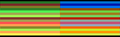 320×200 palette 1
 -
 320×200 palette 2
 -
 640×200
Thus, with the choice of 320×200 vs. 640×200 mode, the choice of palette (1 or 2) and the freely-selectable color 0 in 320×200 modes (see above), each one of these parameters results in a different set of artifact colors, making for a total gamut of well over a hundred colors, of which 16 can be displayed at the same time.
Availability and caveats
The 320×200 variant of this technique (see above) is how the standard BIOS-supported graphics mode looks on a composite color monitor. The 640×200 variant however requires modifying a bit (color burst disable) directly in the CGA's hardware registers, as a result, it is usually referred to as a separate "mode", often just as "the" composite color mode, since its more distinctive set of artifact colors led it to being more commonly used than the 320×200 variant.
Being completely dependent on the NTSC encoding/decoding process, composite color artifacting is not available on an RGBI monitor, nor is it emulated by EGA, VGA or contemporary graphics adapters.
Using the same monitor at the same settings, direct colors are constant from card to card and host system to host system. Artifact colors, on the other hand, tend to drift in hue. (This is unrelated to the hue shift problem encountered in the terrestrial reception of NTSC broadcast signals.) For this reason, the original IBM PC and XT design provides a trimpot labeled "COLOR ADJUST"[14] (on the mainboard, not on the CGA card itself) which modifies the phase difference between the ISA bus' CLK and OSC signals that leaves direct colors constant while changing the hue of artifact colors.
Host systems that lack a "COLOR ADJUST" trimpot, such as the Tandy 1000's internal video hardware, might produce erratic artifact colors and require hue adjustment on the composite color monitor. Later AT systems usually do not provide a proper OSC signal at all, rendering the composite color display completely unusable.
Resolution and usage
Composite artifacting, whether used intentionally or as an unwanted artifact, reduces the effective horizontal resolution to a minimum of 160 pixels, more for black-on-white or white-on-black text, without changing the vertical resolution. The resulting composite video display with "artifacted" colors was thus sometimes described as a 160x200/16 color "mode", though technically is was a method, not a mode.
The low resolution of this composite color artifacting method led to it being used almost exclusively in games, with many of the more high-profile titles optionally, sometimes exclusively, offering graphics optimized for composite color monitors:
-
 Ultima II
 -
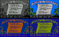 King's Quest

Bugs and errata
In 80-column text mode, bad prioritization of granting access to the single-ported display RAM gives the host system's CPU a higher priority than the video hardware, resulting in display errors ("snow") whenever the CPU accesses display RAM. Prudent programmers compensated by limiting display RAM accesses to the retrace period. This problem is neither present in any other display mode, nor in most other display adapters.
The video controller 6845's row counter being only seven bits wide, display RAM in graphics modes is laid out in a 2:1 interlace pattern, first laying out the data for rows 0, 2, 4, etc., then the data for rows 1, 3, 5, etc., adding additional software overhead for display RAM manipulation. This is unrelated to the NTSC field interlace.
Competing adapters
CGA had two main competitors:
- For business and word processing use, IBM launched its Monochrome Display Adapter (MDA) at the same time as CGA, which produced a higher resolution text display in 80×25 mode, rendering each character in a box of 9×14 pixels, of which 7×11 were the character itself. This produced sharper and more clearly separated characters than the CGA's 8×8 dots text character matrix allowed. Because of this, MDA was often preferred for business use. Also, IBM initially manufactured the MDA card as a printer port/MDA combo card. This meant that users wishing to connect printers to their original IBM PC would have to pay for the MDA card anyway (initially $335), while the CGA card (initially $300) could be left out to save money. While including the CGA card and connecting an existing TV set for use as a monitor allowed users to forgo the purchase of a monitor, this was not significantly cheaper than buying a monochrome monitor (initially $345) and leaving out the CGA card. Also, CGA graphics and especially text on a composite display/TV set were even less sharp than on an RGBI monitor, and the IBM model 5153 CGA color video display that was required to fully exploit the CGA card's capabilities was even more expensive. For these reasons, many original IBM PCs did either not include CGA cards at all, or if they did include them, they also included the MDA card and mostly remained connected to an IBM model 5151 (or third party compatible) monochrome display, leaving the CGA card unused.[15]
- In 1982, the non-IBM Hercules Graphics Card (HGC) was introduced. In addition to an MDA-compatible text mode, it offered a monochrome graphics mode. With a resolution of 720×348 pixels, it had a higher resolution than that produced by CGA. The Hercules adapter's offer of better monochrome graphics and its ability to work with less expensive monochrome monitors made it a desirable choice for many. As early as 1985, emulator memory-resident programs such as SIMCGA were available, allowing the display of most CGA graphics modes (excluding the 160x100/16 and composite modes) in Hercules graphics modes (the result looking like crude dithering).
- Important to the gaming community, the IBM PCjr and its compatible Tandy 1000, released in 1984, featured an onboard "extended CGA" video hardware that extends the video RAM to 32k, thus allowing 16 colors at 320×200 resolution and 4 colors at 640×200 resolution. Similarly but less widely used was the Plantronics Colorplus.
- In 1984, IBM also introduced the Professional Graphics Controller, a —for its time— very sophisticated high-end graphics solution intended for e.g. CAD applications. It was mostly backwards compatible with CGA. The PGC did not however see widespread adoption and was discontinued in 1987.
- Another extension in some CGA-compatible chipsets (including those in the Olivetti M24, the DEC VAXmate, and some Compaq and Toshiba portables) is a doubled vertical resolution. This gives a higher-quality text display and an extra 640×400 graphics mode.
The CGA card was succeeded in the consumer space by IBM's Enhanced Graphics Adapter (EGA) card, which supports most of CGA's modes, and added an additional resolution (640×350) as well as a software-selectable palette of 16 colors out of 64 in both text and graphics modes. Along with this move, the price of the older CGA card was lowered considerably; it now became an attractive low-cost option and was soon adopted by the new PC cloning companies as well. Entry-level non-AT PCs with CGA graphics sold very well during the next few years, and consequently there were many games released for such systems, despite their limitations. CGA's popularity started to wane after VGA became IBM's high-level standard and EGA the entry-level standard in 1987.
Specifications
Connector
The Color Graphics Adapter uses a standard DE-9 connector.
| Pin | Function |
|---|---|
| 1 | Ground |
| 2 | Ground |
| 3 | Red |
| 4 | Green |
| 5 | Blue |
| 6 | Intensity |
| 7 | Reserved |
| 8 | Horizontal Sync |
| 9 | Vertical Sync |
Signal
| Type | Digital, TTL |
|---|---|
| Resolution | 640h × 200v, 320h × 200v |
| H-freq | 15.75 kHz |
| V-freq | 60 Hz |
| Colors | 16 |
References
- ^ [1]; cf. section 1-133, "Color/Graphics Adapter", page 143 of ibm_techref_v202_1.pdf
- ^ International Business Machines Corporation (1983): IBM Personal Computer XT Technical Reference Manual, pages D-42 to D-43.
- ^ Dean et al. (1984): Composite video color signal generation from digital color signals. U.S. Patent #4,442,428
- ^ International Business Machines Corporation (1983): IBM Personal Computer XT Technical Reference Manual, page D-40.
- ^ a b Williams, Gregg (1982): A Closer Look at the IBM Personal Computer. Byte Magazine January 1982, pages 64,68.
- ^ International Business Machines Corporation (1982): You & Your IBM Personal Computer. Sales Brochure, page 4.
- ^ mobygames.com
- ^ mobygames.com
- ^ mobygames.com
- ^ cf. http://vintageibm.net/yahoo_site_admin/assets/docs/techrefv202.zip , section/page 1-142, "Color/Graphics Adapter", page 152 of ibm_techref_v202_1.pdf
- ^ oldskool.org
- ^ oldskool.org
- ^ oldskool.org
- ^ International Business Machines Corporation (1983): IBM Personal Computer XT Technical Reference Manual, page D-3.
- ^ http://vintageibm.net/yahoo_site_admin/assets/docs/byte81_4.14662834.jpg
- ZiffDavis-Net site with info on old display adapters, including CGA (note: inaccurately states Hercules cards offered 4 colors.)
- Comprehensive FAQ on old display adapters (Usenet archive, some details speculated and/or inaccurate)
- IBM PC-Compatible CGA Video Reference — includes technical details
- CGA monitor calibration — Technical information on the IBM 5153 monitor's color decoding and calibration
- IBM Color Graphics Adapter (CGA) (Thor Kildsen)
- IBM Personal Computer Hardware Library: Technical Reference (Revised edition, 1983)
- This article was originally based on material from the Free On-line Dictionary of Computing.
See also
- RGB color model
- Graphics card
- Graphics processing unit
- List of display interfaces
- List of 8-bit computer hardware palettes - CGA section
- Code page 437