Distance fuses
A distance fuse , also known as a proximity fuse or proximity fuse , is used to automatically detonate a military explosive charge at a defined distance from the target object . Distance fuses are used in grenades , military missiles and guided missiles in the tip of the projectile. The first operational radar - Doppler effect -Abstandszünder came in 1943 in the Pacific War in flak grenades used. They were primarily developed by a team of scientists led by Merle Antony Tuve at the Applied Physics Laboratory of Johns Hopkins University in Baltimore , USA , but also on the British side by people like Samuel Curran .
The Americans succeeded as the only warring party in World War II to mass-produce functional stand-off fuses for anti-aircraft shells and to install them in projectiles down to a caliber of 3 inches (7.62 cm). Until shortly before the end of the war, these projectiles were only used at sea or over their own territory to prevent the technology from falling into the hands of the enemy. The detonators supplied to the UK increased the firing rate of V1 - cruise missiles significantly. As a camouflage, the new distance fuse was called "VT Fuze" (variable time fuze). The distance fuse was first used by the Allied land forces for grenades in the Battle of the Bulge in 1944.
Technically, a distinction is made between different types of distance fuses:
- Radio controlled distance detonator. These are the most commonly used type for grenades.
- Optical distance detonators, mostly by laser .
- Acoustic distance detonators, similar to the method used with an echo sounder .
- Magnetic distance fuses (in water)
- Electrostatic distance fuses
- Distance detonators that respond to pressure (in water)
Radio controlled distance detonator
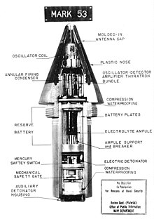
The radio-based proximity fuse was established in January 1943 by the American Merle Tuve patented and based on the radar - Doppler effect . The detonator is located in the tip of the grenade and consists of a small oscillator circuit that functions as both a transmitter and ( Audion ) receiver. The transmission frequency is, for example, 180 to 220 MHz. When approaching the target object, part of the transmitted signal is reflected on it, returns to the oscillator via the same antenna and there leads to interference , i.e. H. to level fluctuations. The interference frequency sinks to zero during the flyby, while the amplitude of the level fluctuations reaches its maximum. If the beat frequency drops from 800 Hz to 200 Hz, for example, this means that the relative speed drops from 600 m / s to 150 m / s. This can be evaluated as an ignition criterion. In the patent by Tuve and Roberts (patent US3166015, filed January 6, 1943) the beat signal is selected, for example, by a bandpass amplifier and is applied directly to the grid of a thyratron which triggers the electrical ignition. It is interesting that this first model already contains several security mechanisms. The electronics were only activated when the gun was fired and the grid bias of the thyratron was initially kept negative for a while, so that a certain flight time had to elapse before the proximity fuse was armed.
Web links
Individual evidence
- ↑ James Brennen: The Proximity Fuze - Whose Brainchild? United States Naval Institute Proceedings, September 1968.
- ↑ Electrostatic distance fuses
