
External load

When external load is referred to aircraft externally carried loads. External loads can be carried by both rotary and fixed wing aircraft , both civil and military. Some world records for rotary wing aircraft are held by the Mil Mi-12 , 40 t external load at around 2,000 m altitude and 30 t at around 3,000 m altitude.
Civilian external loads are, for example, fire water external load containers for helicopters or tree trunks for heli-logging . Examples of military loads are reconnaissance containers , drop tanks and weapons. The article deals specifically with external military loads, as the integration into the carrier platform negatively affects the desired high flight performance. In the past, a number of measures were therefore developed with which the flow resistance of external loads can be reduced. The best-known measure are conformal fuel tanks (CFT) , i.e. additional tanks for airplanes whose shape is directly adapted to the contour of the airplane.
history

Since the Second World War, fighter planes have carried aerial bombs or other loads externally. This was not a problem at the low speeds of propeller-driven planes, most of the time only the automatic cannons were fired, which were mounted internally. When the first jet planes appeared after the war, external armament was very limited as the concept of massive retaliation was pursued. After the change in nuclear strategy, conventional, tactical missions of the fighter aircraft were required, and so the existing F-105 Thunderchief and F-4 Phantom II were equipped with as many suspension points as possible for bombs. The key to this was the Multiple Ejector Racks (MER) , which could hold three bombs side by side. With this, however, a problem arose: the air resistance of the loaded fighter aircraft rose drastically, in return, flight performance, endurance and range fell into the abyss. Often the air resistance of the external loads exceeds the air resistance of the airframe.
The problem was that the aircraft designers gave their machines an aerodynamically efficient shape that at least impressed the audience at air shows , but was apparently completely surprised to learn that the military wanted to hang weapons on them. To correct this rapture, the USAF and the US Navy carried out a series of studies to reduce the drag of external loads, whereby the conformal carriage , i.e. the hull-conforming suspension, turned out to be the most efficient. In the Conformal Carriage Flight Test Program , an F-4B was equipped with a conformal adapter on the lower fuselage, into which Douglas LODE-14 ejectors were integrated. The adapter was available in two versions: One variant could accommodate 9 Rockeye IIs in three rows of three bombs each, the other 12 Mark 82 in three rows of four bombs each. The bombs were half sunk in the lower fuselage of the F-4B. During the 36 test flights, bombs and the flight envelope were tested. Except for minor problems, the program was a complete success. The modified F-4B had 60% less drag and needed less fuel than an original F4, as the adapter improved the area distribution of the F-4B. The top speed with the same payload increased from Mach 1.1 to Mach 1.8. The mission radius increased by almost 50%, the stamina was doubled. The modified F-4B could fly missions for which a standard F-4B would need two 370 gal (1400 L) drop tanks . The handling was identical to the normal F-4B except for the greater weight. Although the upgrade cost a total of only $ 50-75,000 (1971) per aircraft, the USAF and USN refused to adopt the upgrade on the grounds that the F-4 should be retired in 1982.
The knowledge of the program was used in the development of the Panavia Tornado and F-14 Tomcat ; both aircraft carry their weapons close to the fuselage. Strictly speaking, these are not hull-compliant suspensions, but they do reduce air resistance, see below. It was not until the F-15 Eagle that the FAST packs made use of all the advantages of external loads that conformed to the hull. The fuselage-compliant tanks, which were adapted to the aircraft according to the area rule, increase the subsonic range by 230 nm , the combat radius in supersonic by 100 nm, provide 2.5-3 hours of endurance at a 500 nm operational radius, a more than 450 nm higher operational radius with three 2000 pound bombs and more weapon stations. As early as 1975, the McDonnell Douglas was planning different variants of the Fuel and Sensor, Tactical (FAST) packs:
- All full of fuel, conformal fuel tank (CFT)
- Reconnaissance equipment
- Front emitter localization system for Wild Weasel , rear 75% fuel
- EloGM systems at the front , 75% fuel at the rear
- All full of fuel and three / four semi-recessed gun mounts for Mark 84 / Mark 82 below
- Everything full of fuel and below two semi-recessed weapon mounts for BVR missiles
- Front 50% fuel, rear 50% for thrust increases ( JATO ?)
- As a freight container
- Front 30% for barrel weapon, rear fuel
- Spray tanks, possibly for chemical warfare agents
- Air refueling tanks
- Internal weapons bay , Conformal Weapons Bay (CWB)
- Above the tank, below two or three rows of fully sunk weapons, turned by 180 ° and with protective caps over the nose: 2 × 7 M117 , 3 × 7 Snake Eye bomb , 3 × 5 Mark 82 , 2 × 5 Mark 83
Ultimately, only one tank variant with external weapon mounts (pylons) was adopted by the USAF. It was not until 2013, more than 35 years later, that the FAST variant with a weapon bay will be implemented for the F-15SE. In the eighties, so-called blended weapons were still being investigated, which have a shape that conforms to the hull and should act as aerodynamic components. Upward weapon ejection was also investigated, as this is beneficial at low altitude . In the 1970s, future combat aircraft with integrated conformal carriage were also proposed: These would have several longitudinal channels on the lower fuselage in which weapons could be mounted, instead of using external load stations under the wing. However, these radical, aerodynamically sensible concepts did not catch on. Today almost all modern combat aircraft use more or less methods to reduce the air resistance of external loads. Fuel tanks that conform to the hull, so-called conformal fuel tanks, are particularly popular because fuel tanks have to be carried on almost every mission and cause considerable air resistance.
backgrounds
theory
When considering the problem theoretically, one comes across Breguet's range formula . Assuming that the external loads double the aerodynamic drag of the aircraft - in some cases an optimistic assumption - twice the amount of fuel would theoretically have to be carried in order to achieve the same range. If the internal capacity were to be increased by 100%, the result would be an increase in the empty weight of approx. 12%, which in turn would necessitate a further increase in the internal fuel quantity, etc. Consequently, it makes more sense to reduce the air resistance of the external loads.

An older fighter aircraft with four weapon holders with racks for two bombs hanging next to one another has about 2.5 times the air resistance of an unloaded aircraft. The weapons and their interference are already 1.5 times that of the unloaded aircraft. If the weapons are aerodynamically disguised on the suspensions, so to speak, put into an external weapon container, the air resistance drops to about 1.7 times that of an unloaded aircraft. With further measures such as streamlining, the value can be reduced to 1.4 times that of an unloaded aircraft. More radical measures, such as a tandem arrangement, can further reduce air resistance by 1.1 times.
There are various empirical formulas for calculating the air resistance caused by external loads, e.g. B. from the Royal Aircraft Establishment . The air resistance of each external load must be multiplied by an installation factor, which depends on the type of external load station, and multiplied by an interference factor, which depends on the total external loads. The following can be determined:
- The distance from external loads should at least correspond to their diameter in order to weaken the interference resistance
- Weapons should be carried in tandem, as the front shields the rear from the current. Especially important in the supersonic.
- The installation factor for mounting on the fuselage is a maximum of 1.3. The resistance of the external load corresponds to a maximum of 1.3 times the value in the free flow.
- The installation factor for semi-recessed mounting on the fuselage is less than 1. The resistance of the external load is therefore lower than its value in the free flow.
- The negative pressure zone / vortex formation of pylons should be reduced. Critical as pylons can account for around 50% of the additional resistance.
- Hull-mounted weapon containers for carrying bombs are very efficient, with + 6/12% resistance instead of + 30/96% with normal suspension, if more than 4/6 TMD have internal space (subsonic / supersonic).
A weapon bay can reduce the aerodynamic drag of the payload to almost zero, but it creates its own problems: the size and cost of the aircraft increase, the capacity for weapons is limited, the flow resistance of the unarmed aircraft increases due to the volume requirement of the weapon bay, the loading and the transfer of target data is made more difficult and the ejection is aerodynamically challenging, since open shaft doors can reach strong, unsteady currents and sound pressure levels of up to 170 dB.
practice

Specifically, bombs such as the Small Diameter Bomb (SDB) are transported in tandem, and launch rails for external loads are integrated into the aerodynamics of the airframe. The best example of this are launch rails on the wing tips, which eliminates the additional resistance of the pylon. On the Eurofighter or the F-14 , the launch devices on the wing tips or the swivel joint are part of the airframe and cannot be removed. This takes their resistance into account in the performance of the unarmed aircraft. The mounting of weapons directly on the fuselage is also low in resistance, since the pylons are also omitted here, which can account for up to 50% of the additional resistance. Since assembly with pylons on the fuselage is still less resistant than under the wings, combat aircraft are usually loaded from the inside out.
Another possibility is the transport of aerodynamically unfavorable loads in an external weapon container. These are intended for the F-22 and the F / A-18E / F Block III , among others . With the latter, the Enclosed Weapons Pod should be attached to the lower hull. External weapon containers were also planned for the Boeing-Sikorsky RAH-66 , which, as thickened stub wings, were to hold two Hellfire and one ATAS . The desire for a reduced radar reflective surface also plays a role in these platforms.
The application of area-regulated dents on the fuselage of the aircraft is mostly used for fuel tanks, since the space utilization is better than with internal armament. Nonetheless, hull-compliant “bladders” are also used to accommodate weapons, e.g. B. on the F-15SE. Other variants of the FAST packs were not realized, although a low-drag payload is possible for every military requirement.
The use of semi-submerged weapons and tanks is the most efficient way of transporting external loads. The English Electric Lightning should z. B. can carry either a fuel tank or a rocket engine at the semi-submerged lower trunk station. Ultimately, however, only the 1130-liter tanks were procured, which could initially be dropped during flight. The Eurofighter also uses the option of carrying up to four AMRAAM / Meteor missiles half-sunk under the fuselage. The air resistance of the weapons is so less than if they were moving in a free current; In addition, the tandem arrangement reduces the resistance.
System considerations

Eurofighter: four half-sunk weapon stations in tandem and two fixed launch rails

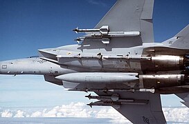
F-16: Two fixed launch rails on the wing tips
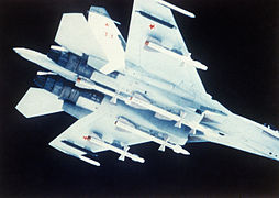
Su-27: Four missiles attached to the fuselage, in tandem between the engines
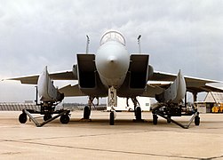
F-15: Four missiles mounted directly in tandem on the fuselage and tank on the lower fuselage
F-15: FAST packs left and right

F-4D: Black Pave Sword laser target holder with flat head for maximum air resistance
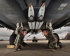
F-15E: Small Diameter Bombs in tandem directly on the lower hull
.jpg)


Gloster Meteor: fuel bubble under the hull

F-15E: With conformal fuel tanks and external loads

F-16D: Above conformal fuel tank on the fuselage, below aerodynamic disaster

B-58: fuel tank with integrated nuclear weapon

Tornado ADV: Four weapons in tandem on the fuselage

F-4D: Aerodynamic Pave Knife laser target container

Tu-22M: A Kh-22 half-sunk under the fuselage


Web links
Individual evidence
- ^ A b c d Flightglobal: Taking the drag out of bombs , August 21, 1982
- ^ A b Pell, Colman: Exploitation of Technology for Military Advantage , Directorate of Science (Air), RTO MP-16, 28-30. September 1998 ( Memento of the original from September 27, 2013 in the Internet Archive ) Info: The archive link was inserted automatically and has not yet been checked. Please check the original and archive link according to the instructions and then remove this notice.
- ↑ NAVAL WEAPONS CENTER CHINA LAKE CA: Conformal Carriage Flight Test Program. Part 2. Weapon Separation , JUN 1973 ( Memento of the original from September 27, 2013 in the Internet Archive ) Info: The archive link was inserted automatically and has not yet been checked. Please check the original and archive link according to the instructions and then remove this notice.
- ↑ a b c d AGARD: Special Course on Fundamentals of Fighter Aircraft Design , January 21, 1988 (PDF; 27.9 MB)
- ↑ a b JTCG / ALNNO: AIRCRAFT / STORES COMPATIBILITY SYMPOSIUM PROCEEDINGDS , 1973 ( page no longer available , search in web archives ) Info: The link was automatically marked as defective. Please check the link according to the instructions and then remove this notice.
- ^ Air Force Research Laboratory: Cooperative Response to Future Weapons Integration Needs , RTO MP-16, 28-30. September 1998 ( Memento of the original from April 6, 2016 in the Internet Archive ) Info: The archive link was inserted automatically and has not yet been checked. Please check the original and archive link according to the instructions and then remove this notice.
- ^ AGARD: Helicopter / Weapon System Integration , July 1997