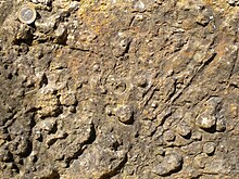
Exposure mark
A stress mark is a deformation in the unconsolidated sediment . This very common structure on the underside of the bank is the result of a Rayleigh-Taylor instability . Instability occurs when a layer of higher density overlies a layer of lower density and the sediment liquefies under the influence of pressure . Earthquakes are considered to be the cause of the liquefaction .
Disambiguation
The term stress mark ( Engl. Load cast , sometimes load structure ) refers to the force exerted by a heavier upper class load , which results in lighter underclass to deformations of the brand . Closely related to stress marks are mass shifts such as “ flame structures ”, “ load waves ” and so-called “anticrests”. An extreme further development are " pseudo-nodules " and " ball-and-pillow structure ", which can sink very deep (up to 6 meters) into the lower layer.
history
Stress marks were scientifically described for the first time in 1895 by T. Fuchs , who at that time still called them flowing beads . He also succeeded in generating the structures experimentally. Later important studies come from HC Sorby from 1908, from P. Kukuk from 1920 and from RR Shrock from 1948.
description
Stress marks form on the underside of a denser upper layer (consisting of sand , coarse sand or gravel ), which is superimposed on a less dense, hydroplastic lower layer (consisting of clay , silt or fine sand). The resulting forms are bumpy, callused, sack-like, warty or protruding. Viewed in profile, they appear as lined up, flattened lobes that protrude into the lower class. The equally spaced lobes have roughly the same size and shape. Flame-like tongues protrude from the lower layer between the lobes. Seen three-dimensionally, the lobes resemble round to elongated cushions, which are separated from one another by narrow indentations. The sequence of praises and tongues can be idealized by a series of semi-ellipses that touch each other at the tip of the tongue. A characteristic wavelength L can then be assigned to the semi-ellipses . This characteristic wavelength depends on the difference in density and viscosity of the two layers. It usually has values between a few millimeters and 10 centimeters, but in extreme cases it can grow to 10 meters.
Occurrence
Stress marks occur in very different facies areas. They are most common in turbidites , but they are also found in fluvial and shallow marine environments. Occasionally they are also found in lake sediments. (Even in layered igneous intrusions Engl. Layered igneous intrusion ) and pyroclastic sequences can be observed. Very good examples of stress marks come from the Borrowdale Volcanic Series in the Lake District and from the Bude formation in South West England .
Emergence
Stress marks arise in muddy-sandy areas of deposits when sandy deposits of different thicknesses press the subsoil to different degrees. Larger rock fragments or other material carried along in the sediment-forming turbidity flow can also generate these pressure differences at the sediment base.
In order for stress marks to arise, there must be an inverse density layer. Such arrangements are unstable in the earth's gravitational field , since their potential energy does not have a minimum. Stress marks are an example of the instability of boundary layers in disturbed density profiles. The instability is known as the Rayleigh-Taylor instability. It is driven by the higher static buoyancy of the lighter lower layer compared to the upper layer.
This instability is initially only potentially present. It also requires the fluidization of the sediment in order to actually appear. The fluidization process means a considerable, if not complete loss of internal cohesion ( yield strength ) for the affected layer . This means that no minimum force has to be applied to deform the respective material. This additional condition was already recognized by Sorby in 1908 (and later again by Shrock in 1948). The fluidization process is usually triggered by shock-like movements such as those that occur in earthquakes . In 1975 Sims was able to link the emergence of pollution marks in lake sediments to historical earthquake events.
meaning
Contamination marks are geopetal structures and thus good indicators of the slope direction of the respective sediment.
See also
literature
- JRL Allen: Sedimentary structures. Their character and physical basis . Elsevier, 1984, ISBN 0-444-42232-3 .
- JRL Allen: Principles of Physical Sedimentology . Chapman & Hall, 1985, ISBN 0-412-53090-2 .
- H.-E. Reineck & IB Singh: Depositional Sedimentary Environments . Springer-Verlag, 1980, ISBN 0-387-10189-6 .
Individual evidence
- ^ T. Fuchs: Memorandum of Academic Sciences, Vienna . tape 62 , 1895, pp. 369-448 .
- ^ P. Thy, JR Wilson: Primary igneous load-cast deformation structures in the Fongen-Hyllingen layered basic intrusion, Trondheim region, Norway . In: Geol. Mag. Band 117 , 1980, pp. 363-371 .
- ↑ JM Anketell et al .: On the deformational structures in systems with reversed density gradients . In: Roczn. Pole. Tow. Geol. Band 40 , 1970, pp. 3-30 .
- ^ JD Sims: Determining earthquake recurrence interval from deformational structures in young lacustrine sediments . In: Tectonophysics . tape 29 , 1975, p. 141-152 .

