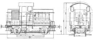
DR V 6001 to V 6003
| DR V 6001 to V 6003 | |
|---|---|
|
Dimensional sketch
|
|
| Numbering: | V 6001–6003 V 16 001–003 (from 1930) |
| Number: | 3 |
| Year of construction (s): | 1924 |
| Retirement: | unknown |
| Axis formula : | B. |
| Gauge : | 1435 mm ( standard gauge ) |
| Length over buffers: | 7,750 mm |
| Length: | 6,060 mm |
| Height: | 4,150 mm |
| Width: | 2,550 mm |
| Fixed wheelbase: | 3,600 mm |
| Service mass: | 30 t |
| Friction mass: | 30 t |
| Wheel set mass : | 15 t |
| Top speed: | 24 km / h |
| Installed capacity: | 118 kW (160 PS) |
| Driving wheel diameter: | 1,000 mm |
| Motor type: | MWM |
| Motor type: | Four-cylinder four-stroke diesel engine |
| Rated speed: | 375 min −1 |
| Power transmission: | hydrostatic |
The V 6001 to V 6003 were three diesel locomotives of the Deutsche Reichsbahn (DR), which were designed for shunting service with hydrostatic power transmission .
history
The three vehicles were produced by the mechanical engineering company Karlsruhe on behalf of the DR , while the diesel engines came from the Mannheim engine works . Similar specimens were previously sold by Motorlokomotiv-Vertriebsgesellschaft mbH Baden (merger of Badische Lokomotivwerke Mosbach, from 1925 Gmeinder & Co. GmbH, Maschinenbau-Gesellschaft Karlsruhe and Motorenwerke Mannheim).
In 1924 the first locomotive was presented at the railway technology exhibition in Seddin, after which the machine is said to have been used in the Schwetzingen repair shop . Two more locomotives were added later. In 1930 the vehicles were redrawn as V 16 001 to V 16 003. There is no information in the literature about the further route of the vehicles. It was only noted that it existed. Presumably, the locomotives that were built before the hydrodynamic power transmission was ready for series production were no longer needed after it was fully developed.
technical features
The locomotive was exhibited at the railway technology exhibition in Seddin, thanks to a detailed description and sketch in Glaser's annals .
The locomotive had a simple sheet metal frame , in whose frame cheeks the cutouts for the axle bearings and the jackshaft were incorporated. The axle bearings were designed as plain bearings . The locomotive body was designed as a front-end construction. The drive motor was housed in the front, larger stem. This was followed by the driver's cab with the controls and a steel bottle for starting the engine. Under the driver's cab was the hydrostatic motor mounted in the frame, which was mounted concentrically with the jackshaft and driven the wheels via this and rod drive. The hydraulic pump and the cooling system for the diesel engine were housed in the rear, short stem . The front end was made narrower than the driver's cab over the entire height in order to ensure a good view from the driver's cab. The free space could be used for circulation.
The locomotive's machinery consisted of a four-cylinder four-stroke diesel engine from Motorenwerke Mannheim with an output of 160 hp at 375 min −1 and the hydrostatic transmission based on the patent from Lenz & Co. The direction of travel was selected using a reversing lever when the locomotive was stationary. When moving off and changing speed, only the handwheel in the driver's cab was operated. With it, a step switch was changed with the same speed of the diesel engine, with which the delivery rate of the hydraulic pump was changed. This consisted of three capsule pumps, at speed level I (8 km / h) the hydrostatic motor rotated at 42.5 min −1 , only one capsule pump was used, at speed level II (16 km / h) the hydrostatic motor also rotated 85 min −1 , two capsule pumps were used and at speed level III (26 km / h) the hydrostatic motor rotated at 1,380 min −1 , and all three capsule pumps were used. The diesel engine had the same speed at all speed levels, the tractive forces at the speed levels were 32 kN, 16.5 kN and 11 kN. The design of the step switch made it possible to switch from speed step to speed step under load without losing traction. When driving in idle, a gear valve had to be operated to avoid impermissible pressures and the braking process of the oil. The diesel engine and the transmission oil were cooled by water.
literature
- Wolfgang Glatte: German Locomotive Archive: Diesel Locomotives . 4th edition. transpress, Berlin 1993, ISBN 3-344-70767-1 .
- KR Repetzki Diesel Locomotives in Glaser's Annalen 1895-1936 , Transpress Reprint, Berlin 1987, ISBN 3-344-00127-2
Web links
Individual evidence
- ↑ a b c Glatte / Reinhardt Diesel Locomotive Archive , transpress-Verlag Berlin, 1993, ISBN 3-344-70767-1 , description of the V 3602
- ↑ Forum site with mention of locomotives
- ↑ a b K.R. Repetzki diesel locomotives in Glaser's Annalen 1895-1936 , Transpress Reprint, Berlin 1987, ISBN 3-344-00127-2 , page 69
