
German dropping ammunition from World War II
A list of the munitions dropped by aircraft of the German Air Force 1935–1945.
nomenclature
The nomenclature of German dropped ammunition largely follows this pattern:
- Type
- Weight class
- Addition (HL = shaped charge, RS = rocket support, F = parachute)
However, it is not always uniform.
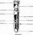
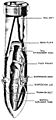
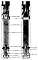
High explosive bomb cylindrical (SC)
In contrast to the bombs of the SD category, the SC bombs had a higher proportion of explosives (mostly around 50-60%), which is why they were classified as mine bombs by the Air Force . In an international comparison, mine bombs and air mines usually had an even larger proportion of explosives in the total weight, which led to other states classifying the German SC bombs more as multi-purpose explosive bombs .
| designation | Weight (kg) | Diameter (mm) | Length (mm) | Length of bomb body (mm) | Explosives (kg) |
|---|---|---|---|---|---|
| SC 50 | 50 (± 4) | 200 | 1100 | 766 | 25th |
| SC 100 it. | 100 | 47-50 | |||
| SC 250 | 250 (± 12) | 368 | 1640 | 1173 | 125 |
| SC 500 | 500 (± 20) | 470 | 2010 | 1432 | 260 |
| SC 500 J | 500 | 470 | 1975 | 245 | |
| SC 1000 "Herrmann" | 1027 (± 34) | 654 | 2580 | 1678 | 530-590 |
| SC 1200 | 1117 | 650 | 2781 | 1905 | 631 |
| SC 1800 "Satan" | 1832 (± 65) | 660 | 3500 | 2674 | 1000-1100 |
| SC 2000 | 2000 | 660 | 3500 | 1200 | |
| SC 2500 "Max" | 2450 | 829 | 3895 | 1700 |
Despite the designation Cylindrical Explosive Bomb , the SC 10 was designated a fragmentation bomb by the German Air Force, which is why it is listed under the fragmentation bombs . The SC-100 it. was taken over from Italian ammunition stocks. The SC 2500 was only used for tests, it was not used. A planned SC 5000 did not get beyond a prototype.

SC 50 Bi
SC 50 YES

SC 50 JB

SC 250

SC 1000
SC 2000
SC 2500


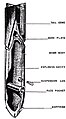
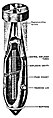
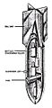
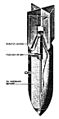
High-walled explosive bomb (SD)
This designation "thick-walled" was used either for typical fragmentation bombs (eg "attack aircraft bomb" SD 2) but also for high-explosive bombs with a greater penetration depth than the SC bombs. The proportion of explosives was around 30%.
- SBe = explosive bomb concrete (also called concrete bomb )
- HL = shaped charge (suitable for fighting tanks)
| designation | Weight (kg) | Diameter (mm) | Length (mm) | Length of bomb body (mm) | Explosives (kg) |
|---|---|---|---|---|---|
| SD 1 | 0.76 | 50 | 170 | 0.11 | |
| SD 1 French | 0.52 | 50 | 160 | 0.06 | |
| SD 2 | 2 | 78 | 303 | 0.225 | |
| SD 3 (8 cm depth) | 3.2 | 80 | 305 | 225 | 0.55 |
| SD 4 / HL | 4th | 92 | 310 | 0.31 | |
| SD 9 (8.8 cm) | 9 | 88 | 578 | 0.8 | |
| SD 9 / HL | 9 | 120 | 310 | 0.85 | |
| SC 10 | 10 | 86 | 545 | 0.9 | |
| SC 10 dw | 10 | 86 | 545 | 0.9 | |
| SD 10 A | 10 | 86 | 545 | 0.9 | |
| SD 10 C | 8th | 76 | 545 | 0.75 | |
| SD 15 (10.5 cm) | 15th | 105 | 637 | 1.75 | |
| SD 50 | 50 (± 4) | 200 | 1090 | 590 | 16 |
| SD 50 Tel. | 50 or 66 | 200 | 1090 | 590 | 15 or 23 |
| SBe 50 | 60 | 200 | 1100 | 590 | 3 to 5.4 |
| SD 70 | 66 | 200 | 1090 | 807 | 24 |
| SD 250 | 250 (± 12) | 368 | 1638 | 890 | 80 |
| SD 250 Tel. | 250 (± 12) | 368 | 1638 | 890 | 78 |
| SBe 250 | 229 | 370 | 1637 | 49 | |
| SD 500 | 480 (± 23) | 396 | 2007 | 1370 | 90 |
| SD 500 A | 450 | 447 | 2022 | 1323 | 180 |
| SD 500 B | 500 | 396 | 2007 | 1420 | 90 |
| SD 500 C | 485 | 396 | 2000 | 1418 | 172 |
| SD 500 E | 480 (± 23) | 396 | 1744 | 1080 | 75 |
| SD 1400 "Esau" | 1400 | 563 | 2840 | 1691 | 325 |
| SD 1700 "Sigismund" | 1704 (± 80) | 660 | 3300 | 2315 | 705 |
The SD 1 French was made from the bodies of captured French 50 mm throwing grenades, the SD 3 (8 cm Wgr) from the bodies of German 8 cm throwing grenades (both with the detonator (73) of the SD 1). The SD 9 (8.8 cm) as well as the SD 15 (10.5 cm) were made from the bodies of 8.8 cm and 10.5 cm HE shells, which meet the quality requirements as artillery shells ( e .g . Dimensional accuracy), manufactured with the detonator eAZ (66) of the SD 10.
Despite the designation S C , the SC 10 was designated as a fragmentation bomb by the Air Force. They were available with a tail unit for the high attack and without a tail unit for the low attack (the detonator then had to be set to delay effect). The SC 10 dw ( d ick w should constantly) with concrete casing with cast steel shrapnel a stronger fragmentation effect. Due to the sensitivity of the AZC (10) (hut) detonator (the detonator was activated after 2.4 seconds after pulling the pin, even if the pin was accidentally pulled on the ground), the remaining SC 10 bombs were transferred to the SD from October 1942 10 A relabelled.
The SD 10 A is a reworked SC 10 with a modified detonator mount for the eAZ detonator (66), the SD 10 C was intended to replace the SD 10 A, which was no longer manufactured from July 1944, there were versions (Pr) made of pressed steel, (L) with bomb body made of a tube with screwed-in grooves, (Stg) made of cast steel , (Te) made of malleable cast iron , (SGe) made of special cast and (PGe) made of perlite cast.
There were several versions of the SBe 50, which vary slightly: version A with 6 kg fragments (made of cast iron or steel) and 5.4 kg of explosives, version B with 12 kg fragments and 5.4 kg of explosives, version D with 12 kg Splinters, 3 kg of explosives, and version E (manufactured using the centrifugal method) with 16 kg of splinters and 5.4 kg of explosives.
The bombs SD 50 Tel., SD 70 Tel. And SD 250 Tel. Had a telescopic tube especially for use in the mud and snow period on the eastern front, which was pyrotechnically extended shortly after being dropped and the bomb was approx. Should detonate 3 meters above the ground. These were - with otherwise the same dimensions - special constructions with a modified internal structure and special detonators that came into effect immediately upon contact with the extended telescopic tube.

SD 2 closed

SD 2 open

SD 4

SD 10

SC 10 dw
SD 15

SD 50

SD 70
SD 500
SD 1700


Attachments for high-explosive bombs
For the German standard bombs (weight class 50 kg, 70 kg, 250 kg, partly 500 kg) there were various add-on parts that optimized the properties of the bombs for certain tasks:
Spike bombs (stabo)

Bomb bodies of a high quality could be provided with a 400 mm (SD 50), 580 (SD 70) or 700 mm long spike at the tip and thus formed the bombs SD 50 Stabo, SD 70 Stabo and SD 250 Stabo. The sting should prevent the target from ricocheting off the target during deep attacks against railways and traffic routes, especially with a heaped embankment. The bomb got stuck in the embankment, the detonation was triggered by a bomb detonator with a delay (to protect one's own aircraft), and long-term detonators or jammers (triggered by shaking the passing train) were also possible.
Dinort bars
The rods named after the Stuka pilot Oskar Dinort were screwed onto the bomb tip of the SD 50, SD 70 (600 mm long), SD 250 or SD 500 (375 mm long) in a similar way to the above-mentioned sting. Dinort rods were used to ensure that the bomb responded by triggering the normal bomb detonator as soon as it hit the tip of the Dinort rod (which had a correspondingly large area). This achieved a certain distance detonator effect, which promised an optimal distribution of the splinters. For the further development of these "distance fuses" specially manufactured "telescopic bombs" were developed (see SD 50 Tel. And SD 250 Tel.)
Baffles

When bombs were deployed from lower heights (40 to 100 meters) against ship targets, the ogive bomb tip often caused an uncontrolled ricochet from the water surface , sometimes even from the sheet metal of the deck , so that the bomb even jumped over the ship and followed the throwing aircraft ( and then endangered it by detonation). The attachment of baffle disks to the bomb tip of the SC 250 or SC 500 did not prevent the ricochet from the water surface, but the bombs were slowed down to such an extent that they overturned lengthways over the water surface and either against the hull of the attacked ship collided (and detonated there by the impact fuse) or sank after a short “flight” distance of 25 to 35 meters next to the ship (and then detonated under water via the delay function of the fuse). In the event of an impact on the deck, the baffle plate should prevent the ricochet and trigger the immediate detonation .
Head rings
In contrast to the baffle discs, head rings should keep the bomb on its trajectory, even below the surface of the water, through the targeted flow separation when entering the water. For the bombs SC 50, SD 70, SC 250 and SC 500, these head rings were supplied separately as an accessory for retrofitting, the larger bombs (e.g. SC 1000, SD 1700, SC 1800 and the large-charge bomb SB 2500) had these head rings on the bomb body ex works.
Jericho device
For psychological warfare, so-called " Jericho devices " could be attached to the tail units of German bombs (SC 50 and SC 250) . These generated a loud whistling when falling, which was intended to demoralize the people in the target area of the bomb.
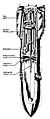
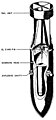
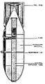
Tank explosive bomb (PC and PD)
- PC = Cylindrical tank explosive bomb
- PD = armored explosive bomb with thick walls
| designation | Weight (kg) | Diameter (mm) | Length (mm) | Length of bomb body (mm) | Explosives (kg) |
|---|---|---|---|---|---|
| PC 500 "Paulina" | 500 | 395 | 2007 | 98 | |
| PD 500 | 500 | 276 | 2100 | 1385 | 32 |
| PD 500 RS | ? | ? | ? | ? | |
| PC 1000 "Pol" | 988 (± 50) | 500 | 2100 | 1476 | 152 |
| PC 1000 RS | 1000 | 398 | 2220 | 1190 | 65 |
| PC 1400 "Fritz" | 1408 (± 55 kg) | 562 | 2836 | 1932 | 320 |
| PC 1600 | 1600 | 660 | 2812 | 1667 | 230 |
| PC 1800 RS "Panther" | 1800 | 536 | 2690 | 1667 | 220 |

PC 500

PC 500 RS

PD 500

PC 1000
PC 1000 RS

PC 1400
PC 1600

PC 1800 RS


Large cargo bomb (SB and SA)
This category can be counted as mine bomb .
- SB = special bomb (or high-explosive bomb?)
| designation | Weight (kg) | Diameter (mm) | Length (mm) | Length of bomb body (mm) | Explosives (kg) |
|---|---|---|---|---|---|
| SB 1000 | 1000 | 660 | 2650 | 1530 | 850 |
| SB 2500 (Al) | 2500 (± 70) | 825 | 3895 | approx. 2800 | 2000 |
| SB 2500 | 2370 (± 70) | 785 | 3693 | approx. 2800 | 1570 |
The bomb body of the SB 2500 (Al) was made of cast aluminum or of welded aluminum sheets with a welded tail unit made of aluminum. In the course of saving aluminum as a material essential to the war effort, the SB 2500 was made from sheet steel with a welded steel head, as is customary with the other bombs. The dimensions have been reduced to accommodate the newer bombers such as the He 177 and Do 217 . From December 1942 on there was SB 2500, which instead of Fp 60/40 were filled with Trialen 105 for use against ship targets, these bombs were approx. 140 kg heavier.
Incendiary Bomb (B, BC)
- B = incendiary bomb
- BC = incendiary bomb, cylindrical
| designation | Weight (kg) | Diameter (mm) | Length (mm) | filling |
|---|---|---|---|---|
| B 1 E | 1 | 50 | 350 | 0.68 kg (electron + thermite) |
| B 1.3 E. | 1.3 | 50 | 350 | 0.68 kg (electron + thermite) |
| B 2 single | 2 | 50 | 525 | 0.68 kg (electron + thermite), 0.06 kg PETN |
| B 2.2 single | 2 | 50 | 525 | 0.68 kg (electron + thermite), 0.1 kg PETN |
| B 4 | 4 to 4.5 | 80 | 700 | 1.2 |
| B 10 | 11 | 115 | 1070 | 3.5 |
| Brand C 50 A | 41 | 200 | 1100 | 12 kg fire mass |
| Explosive fire C 50 | 50 | 200 | 1100 | 6.5 kg mp 60/40, 73 electron fire bodies |
| Brand C 250 A | 185 | 368 | 1654 | 65 kg fire mass |
| Flam C 250 | 125 | 368 | 1652 | 74 kg of flame mixture |
| Flam C 500 | 225 | 470 | 1765 | 157 kg flame mixture |
B 1

B 2.2 single
Brand C 50 A

Brand C 250 A
Flam C 250 A
Flam C 500


The incendiary bombs B 1 E and B 1.3 E consisted of an electron shell and a thermite ignition charge (see also stick incendiary bomb ). The B 1 E had an aluminum head section; due to better penetration (and to save aluminum) it was replaced from 1943 by the B 1.3 E with a steel head section. Outwardly indistinguishable, there were the versions B 1 EZ and B 1,3 EZ, in which an explosive dismantling charge of 8 or 15 grams PETN was incorporated to prevent attempts to extinguish the fire, which was carried out 1/2 to 5 minutes after the Impact detonated.
The incendiary bomb B 2 EZ consisted of the B 1 E with an extended tail unit and a preassembled explosive device with 60 grams of nitropenta. Upon impact, the incendiary bomb was set on fire as usual, and at the same time the warhead was detached using a powder charge and thrown a few meters away. After a 2, 4 or 6 minute delay, the ejected warhead detonated. A further development was the B 2.2 EZ, here - with the same overall dimensions - the warhead in front was enlarged to approx. 100 grams.
There were four different versions of the B 4 incendiary bomb, which were externally identical (perforated sheet steel body with cast iron head and tail unit) and differed only in the different fillings, which each had a different fire behavior. Thrown together in an attack, the different fire behavior together with the strong smoke development in all four models should make the extinguishing work more difficult: The B 4 CH had a slowly burning thermite mixture with naphthalene , which burns with an "igniting flame" for about 4 to 5 minutes, whereby the naphthalene leaks while burning and increases the area of the fire. The bomb could only be extinguished by using large amounts of sand and water. The B 4 Chl was filled with pitch, potassium perchlorate and ammonium nitrate and burned out of the holes in the incendiary bomb with flashes of flame. This variant could practically not be extinguished with the quantities of sand and water available for the self-protection forces. The B 4 D / Np 30 had comparable fire behavior and extinguishability, but was filled with dinitroacenapthen (diacen) and PETN with montan wax. The B 4 Na was explicitly designed to endanger the extinguishing forces with a filling made of cast sodium in an airtight casing made of sheet zinc. The sodium burned with a blazing flame and formed - similar to the electron incendiary bombs - a hot cake of molten metal. Oxygen gas explosions occurred during attempts to extinguish the fire with water.
The incendiary bombs C 50 A (like the C 250 A) contained liquid incendiary material. During use, you should cover a target area of 15 meters (C 50 A) or 30–40 meters (C 250 A) in diameter with cinder blocks that burn for about 10–20 minutes. In the first version (manufactured until October 1942), a phosphorus-carbon disulfide solution was used as an ignition mixture to mix the fire. Since the bomb was in a vertical position in the top of the bomb during the flight and frozen due to the low temperatures (flight at high altitude), the white phosphorus required for ignition was later placed in the incendiary material in glass ampoules.
The high-explosive incendiary bomb C 50 contained in the head an explosive charge made of mp 60/40 and in the cylindrical part 6 each 1.07 kg heavy and 67 each 55 g heavy electron incendiary. After the bomb had hit, the incendiary electron was first ejected, and the explosive charge detonated about 3–4 seconds later.
The incendiary bombs Flam C 250 and C 500 contained a liquid incendiary mass of 30% gasoline and 70% crude oil as well as a decomposing charge of TNT and should have a flame of 15-20 meters (Flam C 250) or 30-40 meters (Flam C 500) in diameter with a burning time of 10 to 15 seconds.
Makeshift incendiary bombs
Makeshift incendiary bombs were also made by the troop workshops. One target was, for example, the wooden bridges built by Soviet forces over the Kerch Strait . Ordinary bombs had little effect against this construction. To produce a suitable bomb, two 200-liter gasoline barrels were usually welded together, a front panel and a temporary tail unit were made from sheet metal . These bomb bodies were filled with a gasoline / oil mixture and rags. Two to four small incendiary bombs were attached to the side for ignition. When the weather was suitable, these bombs were not dropped directly on the target, but on the surface of the water on the side facing the wind. Upon impact, the bomb body broke and released the contents, which were ignited by the small incendiary bombs. This drifted against the wooden bridges and set them on fire.
Air mine (LM)
.jpg)
These are air-deployable sea mines that are dropped on parachutes; not to be confused with aerial mines .
| designation | Weight (kg) | Diameter (mm) | Length (mm) | Explosives (kg) |
|---|---|---|---|---|
| LM A | 697 | 660 | 2.133 | 306 |
| LM B | 987 | 660 | 3,048 | 697 |
| LM C | 600 ± 25 | 660 | 2720 | ? |
| LM F | 1050 | 638 | 2,337 | 278 |
LM A and LM B were air-deployable ground mines, LM C and LM F air-deployable anchor mines, which could be equipped with different remote ignition devices. The drop was made from airplanes, the fall was slowed down by a parachute that was released when it hit the surface of the water. The mine sank to the bottom (LM A and LM B) or is held under the water surface at a depth of up to 300 meters by the base weight and an anchor rope in a certain water depth (LM C and LM F) and was overflowed by a ship Contactless triggered by various sensors (magnetic, acoustic, magnetic-acoustic or by pressure change-magnetic). As variants LM A (S), LM B (S) and LM F (S), these mines could also be used from watercraft without a parachute.
The LM A was under development between 1928 and 1934. The planning for the LM B should have been in the same period. In addition, work was also carried out on a project for LM D, which was ended early on before completion. However, the findings found input for the LM F.
Bomb mine (BM)
BM 1000 is an in-house development to complement the sea mines LM A and LM B, which, in contrast to these, was dropped with a tail fin without a parachute.
| designation | Weight (kg) | Diameter (mm) | Length (mm) | Explosives (kg) |
|---|---|---|---|---|
| BM 1000 "Monika" | 907 | 660 | 2,000 (bomb body only) | 726 kg HEXANITE |
The BM 1000 was laid from an aircraft, sinks to the bottom and is triggered without contact by various sensors (magnetic, acoustic, magnetic-acoustic or by pressure change-magnetic) when a ship overflows.
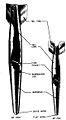
Air torpedo (LT)

This designation was used for self-propelled air-launchable torpedoes in the water.
| designation | Weight (kg) | Diameter (mm) | Length (mm) | Explosives (kg) |
|---|---|---|---|---|
| LT 350 | 350 | 500 | 2,600 | 120 |
| LT F 5 / LT 5a | 685 | 450 | 4,960 | 200 |
| LT F 5b / LT I | 750 | 450 | 5,150 | 200 |
| LT F 5w | 936 | 450 | 5,460 | 170 |
| LT F 5i | 885 | 450 | 5,250 | 175 |
| LT F 5u | 752 | 450 | 5,160 | 200 |
| LT 850 (Type 91 Mod 1 or Mod 2) | 784 or 935 | 450 | 5,275 or 5486 | 150 or 205 |
| LT 950 "Angel of Peace" | 970 | 450 | 5,150 | 200 |
| LT 1200 | 1,295 | 533 | 5,567 | 300 |
| LT 1500 | 1,502 | 533 | 6,430 | 300 |
The LT 350 (also known as the “parachute motor bomb”) was adopted by the Italian armed forces and used by German torpedo pilots only in the Mediterranean region. At low airspeeds from great heights (over 100 m) it was used indiscriminately to combat ship congregations. After being dropped from the parachute, it came loose when it hit the surface of the water, the electric motor started with only 3.5 HP and the LT 350 ran irregular spirals for about 1 hour in an area of 1000 × 800 meters, initially at one speed of 7 m / s, later only 3 m / s, the total distance covered was approx. 15 km.
The LT F 5 was the German replica of the Norwegian Horten torpedo introduced for sea pilots in 1935. With very limited operational values (dropping from 15 to 25 meters at a maximum of 140 km / h), it represented no progress compared to the air torpedoes used at the end of the First World War. With the improved version LT F 5a, the dropping height could be increased to up to 50 meters With launch speeds of up to 260 km / h, it could now also be used by the He 115 torpedo aircraft .
The LT F 5b (also referred to as LT I) arose from the LT 5 a by enlarging the air tank and increasing the machine's performance; it was the main air torpedo used by the German Air Force, which could be used at different speeds / ranges: at 2,300 meters with 40 knots, 3,500 m at 33 kn or 7,500 m at 24 kn.
A lack of success (and lack of emphasis on the part of the navy, only from this LTs were used until the end of 1940) in the first days of the war led to a decision by the Führer to discontinue additional purchases, so that the stock of operational LTs dropped to below 40 in October 1940 . Successes of other nations (British LTs against the French battleships “Strasbourg” and “Richelieu” July 1940, paralysis of the “Bismarck” by the British LT in May 1941, deployment of Japanese LTs in Pearl Harbor and in the sinking of the “Prince of Wales” and “ Repulse ”in December 1941) led to a revision of this decision, but since not enough air torpedoes of its own were available, Italy supplied air torpedoes to the German Air Force from 1940, which were introduced as LT F 5w and LT F 5i.
As part of the Yanagi ("pasture") missions, submarines and the like were used by Japan. a. also technical documents and individual copies of the Japanese LT type 91 Mod 2 were delivered to Germany and in autumn 1942 70 Japanese air torpedoes type 91 came to Germany with a blockade breaker . On December 25, 1941, the war diary of the naval war command noted that the testing of the "Japanese aircraft torpedoes (German name LT 850)" had started at the testing site in Travemünde, but that they would probably not be used due to insufficient numbers. The "LT 850" is also listed in a comparative table of the Torpedowaffenplatz (TWP) of the Luftwaffe from October 24, 1942, but it was never introduced to the Luftwaffe.
The combination of the LT I and the glider L 10 ( "Friedensengel" ) was called LT 950. In tests in 1943, when it was dropped from a height of 800 meters, an airway of 2,300 meters could be reached, at the end of which the torpedo was separated from the glider and continued to run.
As early as 1938, attempts were made to use the so-called Walter drive for the LTs. The LT F 5u (also known as LT II) used the drive motor of the F 5b, but the drive gas was generated by the “Walter process” (decomposition of high percentage hydrogen peroxide). The advantage, in addition to an enormous increase in performance (running distance 5,000 m at 40 knots or 12,000 m at 24 knots), was the elimination of the telltale bubble trail, which made it possible to evade the compressed air-powered torpedoes. The drive of the LT 1200 and LT 1500 was also based on the "Walter method", but a recoil drive (rocket principle) was used here. These LTs with the standard diameter of naval torpedoes were supposed to reach distances of 1,500 (LT 1200) or 2,000 (LT 1500) meters at 45 knots, but did not get beyond the experimental stage.
Bomb Torpedo (BT)
| designation | Weight (kg) | Diameter (mm) | Length (mm) | Explosives (kg) |
|---|---|---|---|---|
| BT 200 | 220 | 300 | 2395 | 100 |
| BT 400 | 435 | 378 | 2946 | 200 |
| BT 700 A | 780 | 426 | 3500 | 330 |
| BT 700 B | 755 | 456 | 3358 | 320 |
| BT 1000 | 1180 | 480 | 4240 | 710 |
| BT 1400 | 1510 | 620 | 4560 | 920 |
| BT 1850 | 1923 | 620 | 4690 | 1050 |
Bomb torpedoes are non-propulsion torpedoes that were dropped in low flight shortly before the target and cover the remaining distance with only kinetic energy. No bomb torpedoes were actively used in combat.
BT 1400 and BT 700

Light bombs (BLC and LC)
- BLC = Cylindrical Flash
- LC = light cylindrical
Flash bombs produce light as bright as day for an instant to enable reconnaissance aircraft to take aerial photos at night.
Parachute flares open the parachute a few seconds after being dropped and illuminate the ground as they float down, braked.
| designation | Weight (kg) | Diameter (mm) | Length (mm) | Explosives (kg) |
|---|---|---|---|---|
| BLC 50 | 36–62.5 kg, depending on the version BLC 50 - BLC 50C | 200 | 1088 | 4–36 kg aluminum pyro grinding or aluminum grit, depending on the design |
| LC 50 F | 19–42 depending on the version LC 50 F / A - LC 50 F / G5 | 200 | 1088 | 19–33 kg pyrotechnic flare, depending on the version |
Fog bomb cylindrical (NC)

Designation for smoke producing on the ground smoke bombs .
| designation | Weight (kg) | Diameter (mm) | Length (mm) | Explosives (kg) |
|---|---|---|---|---|
| NC 50 | - | - | 650 | Luminous powder |
| NC 250 | - | - | - | - |
Guided missiles
The German Air Force also used several types of guided missiles without their own propulsion, primarily against ship targets:
- Fritz X , also X-1, PC 1400X or FX 1400, a steerable bomb developed from the SD 1400
- Henschel Hs 293 , a steerable glide bomb developed from the SD 500
- Blohm & Voss BV 246 hailstone , a steerable glide bomb
See also
swell
- Air Force Service Regulations L. Dv. 4200 "The German dropping ammunition"
- http://www.warbirdsresourcegroup.org/LRG/bombs.html
- US Military Arms Research Service: "OP 1673A German Underwater Ordnance Mines"
- OP 1666 "German Military Ordnance" (June 11, 1946) Volume 1 https://de.scribd.com/doc/235457065/German-Explosive-Ordnance-Vol-1
- OP 1666 "German Military Ordnance" (June 11, 1946) Volume 2 https://de.scribd.com/doc/235455909/German-Explosive-Ordnance-Vol-2
literature
- Wolfgang Thamm: Air bombs. The development of explosive devices and incendiary bombs in the Air Force. From the simple aerial bomb to the modern drop ammunition and their uses - with a comparison of the developments in England, the USA and Russia as well as other countries . Bernard & Graefe Verlag, Bonn 2003, ISBN 3-7637-6228-0 .
- Wolfgang Fleischer: German dropping ammunition until 1945. Explosive bombs, incendiary bombs, special dropping ammunition, dropping containers, detonators . Motorbuchverlag, Stuttgart 2003, ISBN 3-613-02286-9 .
- Wolfgang Fleischer: German dropped ammunition in World War II. Basic knowledge of bombs, containers, air torpedoes, mines, packaging and detonators . Helios-Verlag, Aachen 2015, ISBN 978-3-86933-132-4 .
- Karl R. Pawlas: Ammunition Lexicon . Volume 3: German bombs . 2nd Edition. Journal-Verlag Schwend GmbH, Schwäbisch Hall 1992.
- Friedrich Lauck: The air torpedo. Development and technology in Germany 1915–1945 . Bernard & Graefe Verlag, Munich 1981, ISBN 3-7637-5230-7 , ( Defense Technical Handbooks ).
Individual evidence
- ↑ Photo of a type SC 50 bomb with siren on the bomb tail ( Memento from September 4, 2017 in the Internet Archive )