Differential gear

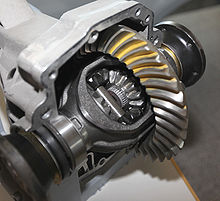
Outside a second bevel gear to drive the differential gear via its planet carrier (also cage or basket ).
The differential gear (or differential gear ), and differential gear or shortly differential (or differential ), is a planetary gear (planetary gear) to a drive and two power take-offs ( transfer gearbox ).
history
Epicyclic gears have been known since ancient times. The Antikythera mechanism had a planetary gear as a summing gear, in the Chinese compass car a subtraction gear between two parallel wheels of the same size served to indicate a direction. The differential is a distribution planetary gear and was first demonstrated by Leonardo da Vinci . It was invented as a differential gear for vehicles in 1827 by the French Onésiphore Pecqueur (1792–1852).

application
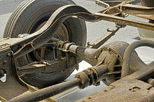
The differential is most often used as an axle differential in automobiles . Its purpose there is to drive two wheels so that they can turn at different speeds in curves but with the same propulsive force.
The central differential has the same purpose in all-wheel drive vehicles in which the power is to be distributed over two or more driven axles.
Structure and mode of operation
The differential gear, like its basic type, the planetary gear (with internally toothed ring gear) (first picture, below), has three coaxial shafts. Its specialty, however, is that the stationary ratio usually has the value i 0 = −1. The transmission ratio between the two central shafts is referred to as the stationary transmission when the planetary gear carrier (web, cage or basket) is held. The gear then does not differ from the so-called stationary gear , which has no rotating shafts. With i 0 = −1, the gearbox distributes the output power from the web to the two central shafts with the same torque each in three-shaft operation . Because the two output gears are the same size, the gearbox structure is symmetrical (pictures two to five, below).
Planetary gear (planetary gear) with internal gear (internal gear teeth)
Bevel gear differential gear , in a straight ahead vehicle: same speeds of the driven shafts
helical -Differentialgetriebe
The bevel gear differential (second and third picture) gets by with four wheels and is the most commonly used. Inside the planet carrier (also known as a cage or basket) the bevel gear is symmetrical: on the right and left there is a bevel gear connected to the driven shafts. The cage carries several bevel gears (usually two) that mesh with the driven bevel gears around its circumference.
Clamps with large wheels number are spur -Differentialgetriebe (fourth image) in which the epicyclic gear are two each to each other and the shaft pinions meshing spur gears, and the helical gear -Differentialgetriebe (fifth image) in which the waves act on peripheral helical gears, coupled to one another via spur gear are.
In all designs, the planetary gear carrier is designed in a ring or box shape. It carries a gear through which it is driven. But it can also be driven via a hollow shaft.
Differential gears in automobiles

Axle differential
If the differential gear is used on a driven axle of a motor vehicle, it is referred to as an axle differential . It balances the speeds between the two wheels. When driving straight ahead, the two smaller gears in the gap in the axle do not turn, but revolve with the large gear so that their effect is neutral. When cornering, on the other hand, they rotate in opposite directions around their axes, so that the wheel is driven a little faster in the outer radius and the other a little slower. Its standard translation is i 0 = −1. If you hold the planet carrier (for example by engaging a gear with the motor stopped), lift the wheels and turn one of the wheels, then the other rotates at the same speed in the opposite direction.
Central or center differential
For vehicles in which all wheels are driven ( all-wheel drive ), additional transfer cases are required: initially one axle differential for each additional driven axle, as well as central or longitudinal differentials to distribute the engine drive to several axles. A four-wheel drive vehicle has two axle differentials and one center differential.
Like axle differentials, central differentials can have a stationary ratio of i 0 = −1. Their torque distribution between the axes is 1: 1 or 50% to 50%. However, central differentials are also built with stationary ratios other than 1: 1. The rear axle often receives a higher drive torque than the front, which is an advantage when accelerating and on inclines. The distribution is for example 65% to 35%. Such an asymmetrically acting differential is also asymmetrically constructed, such as the epicyclic gearing with ring gear (above picture row: first picture; driven is the web) or with differently sized crown gears and spur gear pinions.
Axle differentials in motor vehicles
The differential gear is usually located between the wheels. The planetary gear carrier is almost always permanently connected to a wheel of a driving gear stage. If the motor is installed transversely, this is a spur gear , if the motor is installed lengthways, it is a bevel gear, and if it is driven by a cardan shaft, it is almost always a hypoid gear . With the latter, the axes of the bevel and ring gears do not intersect, the cardan shaft is a little lower. Before the hypoid gearing established itself, there were also worm gears (Peugeot).
The driven shafts lead to the wheels. Both wheels are driven with the same amount of torque, even if - as when cornering - they turn at unequal speed. When turning at the same speed, the differential gear wheels do not cause any loss of power or wear, since they do not move among each other. If one of the wheels stops completely, the other turns twice as fast as the rotating wheel carrier (third picture). This occurs when starting off, namely when one of the two wheels loses its static friction with the ground, for example on mud, snow and the like. This wheel then “spins” and both wheels no longer transmit any forward driving torque. Even in fast corners, the inner wheel can be relieved to such an extent that it spins. A limited slip differential can prevent this: the compensating effect is prevented by rigidly connecting the two drive shafts (full lock) or reduced by targeted friction. In the latter case, part of the power is transferred to the driving wheel and the rest is converted into heat in the transmission. Full locks are almost only found in off-road vehicles. When the lock is activated, the wheels turn at the same speed, the torque is distributed to the wheels depending on the road grip. If the full lock is used on the road or other good surface, the drive train can become warped and damaged, as the different distances in curves can only be absorbed by the slip of the tires.
The stunt popular in action films of balancing a car on two wheels while driving and driving it also only works with a differential lock for the reasons mentioned.
kinematics
The basic speed equation ( Willis equation )
the epicyclic gear is simplified with the stationary transmission to
- .
This means that in every operating state the sum of the speeds of the two driven vehicle wheels (index 1 and 2) is equal to twice the speed of the rotating wheel carrier (index S), or that the rotating speed of the rotating wheel carrier is the arithmetic mean of the wheel speeds.
See also
- Cone differential
- Compass car as a historical application
- Ball differential
- Cutting table
- Limited slip differential
- Synchrodrive
- Torsen differential
- Transaxle
Web links
- www.ArsTechnica.de Limited slip differentials, animations, descriptions of various differentials
- www.howstuffworks.com Animation of the open differential (requires Flash plug-in ; 105 kB)
- Historical US educational film on how a differential works (requires Flash plug-in )
- The differential in action
- How Differential Steering Works (educational film, 1937, English) on YouTube
Individual evidence
- ↑ Encyclopedia Britannica online: [1]
- ↑ http://m.audi-quattro-highlights.de/de/aqh/Technologien/Kronenraddifferenzial


