Epicyclic gears
Epicyclic gears (or planetary gears ) are gear or friction gears which, in addition to shafts fixed to the frame, also have axes that rotate on circular paths in the frame . Accordingly, a distinction is made between the central or sun gears mounted on the axles fixed to the frame and the epicyclic or planetary gears mounted on the rotating axles . The wheels turning on the revolving axes orbit a central wheel similar to how planets circle the sun . The web , which carries the rotating axes, in turn rotates around an axis fixed to the frame.
Epicyclic gears are compact gears with the special feature that the axles fixed to the frame (or shafts in the case of torque transmission) are aligned with one another . Another special feature is the i. d. Usually used three-shaft operation (the third shaft carries the web, which can therefore also be the drive or output ).
Basic structure
A simple stationary gear (no rotating axles) has a minimum of two shafts and is single-stage (only one pair of wheels). An epicyclic gear train has at least two shafts and one rotating axis and is two-stage. Two shafts fixed to the frame are required in technical applications, one driving and one driven shaft are required. The rotation of the wheel ( planet wheel U, pictures below) must be coaxial to both circled wheels (1 and 2) with which it is paired. As a result, these two wheels that rotate fixed to the frame are so-called central wheels . And both and the web (S), which carries the axle with the rotating wheel, are coaxial.
Different designs result from the shape of the second central gear (2) and the fact that a simple planetary gear (U) or pairs of planetary gear (U1 and U2) are used. If the second central gear is a ring gear , the gearbox is particularly narrow (simple planetary gear U).
1 and 2: central gears , S: web, U: planetary gear,: radius ,: peripheral speed (speed perpendicular to the radius)
Special design:
bevel gear differential gear
The large gear is not part of this special epicyclic gear.
If the revolving axis is parallel to the shafts fixed to the frame and all the wheels are spur gears , the wheels appear as circular bodies in the axis-perpendicular section. The revolving gear orbits the externally toothed central gear like a planet, which has led to the general, but not always appropriate, designation of epicyclic gears as planetary gears. One speaks of the planet gear orbiting the sun gear .
In the bevel gear differential , the most commonly used epicyclic gear, the center line of the revolving axis intersects the central center line fixed to the frame at right angles. Its designation as a planetary gear is not appropriate in the above sense. The two central gears are mirror images of the same bevel gears . The planetary gear is also a bevel gear, the web has the shape of a cage.
Operating modes
In general, an epicyclic gearing has three shafts, but one of them is often held in place (two-shaft operation), for example the web (see above: second illustration or below: animation). If the sun gear is driving, the ring gear is the driven one and vice versa. Which shaft / wheel is held and which one / s serves as drive or output depends on the construction task to be solved.
In certain applications, all three shafts rotate (three-shaft operation). Then two are driving and one is driven (addition gear) or vice versa (distribution gear).

Two-shaft operation
In two-shaft operation, the gear is inevitable ( degree of operation F = 1 ). When driving one shaft, the rotation of the second is clear.
A distinction is made between stationary transmission and circulating transmission:
- With the stationary transmission , the spider shaft stands still and the two central gear shafts (i.e. the sun gear and the ring gear) move. The stationary shaft can be permanently connected to the housing or held in place by a brake or an overrunning clutch.
- One of the two central gear shafts is at a standstill in the circulating transmission . The drive and output take place via the rotating central gear shaft and the spider shaft.
Three-shaft operation
In three-shaft operation, the gearbox initially runs at F = 2 . It works as a summing gear or distribution gear:
- In the case of the summing gear , 2 shafts drive and 1 shaft is driven. An example is the summing gear in the rear hub of an electric bike . The drive speeds are freely selected, the output speed is therefore clear. By specifying the two drive movements, inevitability ( F = 1 ) is finally guaranteed.
- In the case of the distribution gear , one shaft drives and two shafts are driven. The speed ratio of the two output shafts must be specified. The best-known example of a transfer gear is the differential gear on a motor vehicle. Here the speed ratio is determined by the wheel spacing and the curve radius. The frictional contact of the wheels with the ground finally ensures inevitability ( F = 1 ). In contrast to two-shaft operation, the input and output torques of the shafts only support each other. Because M S + M 1 + M 2 = 0, the housing remains torque-free (see section on torque transmission ).
Self-locking
Even simple planetary gears are capable of self-locking, i. H. Torques can only be transmitted in one drive direction. With a given static ratio ( i 0 ) and efficiency ( ), this is a range of , i.e. with i 0 in the vicinity of +1.
Multiple or coupling gear
Often not only the simple planetary gear set described here is referred to as an epicyclic gear , but also a combination of several planetary gear sets connected one inside the other or one behind the other based on this basic design. One example is a hub gear on a bicycle, in which more than the three gears that can be achieved with a simple planetary gear set are possible with a multiple gear set.
Further examples of multiple gears are the Ravigneaux set or the Lepelletier gear .
kinematics
Kutzbach plan
The gear ratios on the epicyclic gears can be clearly illustrated with the help of the Kutzbach plan and determined graphically.
Willis equation
A single equation, the so-called Willis equation, is sufficient for the analytical representation :
- .
This contains the so-called stationary transmission of the planetary gear, which describes the speed ratio between the two central shafts 1 and 2 when the web S is held:
- .
Most of the time, the two central gears on the same axis have opposite directions of rotation and the stationary gear ratio is negative (so-called minus gear , opposite: plus gear ). Each of the two central wheels can be the driving wheel 1 or the driven wheel 2.
In the following, the stationary gear ratio required for the Willis equation is determined from the rolling radii of the gear wheels. The approach on which the Kutzbach plan is based is used for this purpose: The speed of a rotating wheel U (see figures under Basic Structure ) runs linearly along its radius shown in red (including its rear addition to the diameter) . This generally applies to rotating circular surfaces, the center of which is moved perpendicular to the radius. In default of two of the three peripheral speeds and can be from the associated connecting line to the third peripheral speed closed.
For the types with ring gear or planetary gear pairs (see pictures at the beginning of the article) the peripheral speed of the respective 1st central gear is obtained according to the two-point form of the straight line equation
- or .
The transition to the corresponding speeds follows
- or .
For the stationary transmission (ie for the braked bridge) it follows
- or .
This parameter allows to describe both types with the equation named after R. Willis .
The Willis equation applies regardless of how the epicyclic gear is built inside. The rotating wheels are not detected by it. With the stationary transmission between two of the three shafts fixed to the frame, the remaining speed ratios between the shafts fixed to the frame are determined. This can be explained as follows: Every movement of a planetary gear can be viewed as a superposition (superposition) of two partial rotations. A partial rotation results when the web is held in place with the stationary ratio i 0 . This is superimposed by the rotation of the entire planetary gear with web.
In two-shaft operation, there are six combinations for a driving, a driven and a fixed shaft. In the following table, for example, the Willis equation has been rearranged for each of these six cases, with that between the sun gear (driving) and ring gear (driven) being selected as the stationary gear ratio:
(Since the number of teeth on a ring gear has a negative value by definition, the example is negative: minus gear ).
With non-stepped rotating wheels, the relative speed of the rotating wheel compared to the web (minus gear set) is calculated from:
This formula can also be used to calculate the relative speed of the rotating wheel of a plus gear set that meshes with the ring gear.
The number of teeth and the number of rotating wheels are irrelevant for the stationary gear ratio , but have an influence on the speed of the rotating wheels and the maximum torque that can be transmitted.
Torque transmission
The relationships between the torques can be derived with a simple lever model or from a power balance. A friction-free transmission is required here, i.e. an efficiency of 100%. The lever model shown on the right applies regardless of the speed. If the torque of the spider shaft is specified, and . With the stationary ratio defined above , the torque ratios follow
- and
- .
It follows from this for the third ratio
- .
In the power balances and the ring gear 2 or the sun gear 1 is assumed to be stationary. The stationary wheels do not transmit any power. This results in the same torque ratios. From the last two equations it can be seen that the torque ratios valid for all speeds are equal to the negative reciprocal of the speed ratios in the corresponding standstill cases.
To describe the operating state of a planetary gear, one torque and two speeds are sufficient (see Willis equation).
Power flow
Each shaft of a planetary gear can be the sole input or output shaft. This means that three shaft combinations are possible with power split or power summation. The graphic on the right assigns the six different operating modes to the - level. The services are shown as right and high components of the red arrows ( or ) and as blue arrows ( ) to scale and with signs. The torque of each shaft is constant at all operating points, where is set; that is, in the right half-plane , the hollow shaft 2 is the output shaft. In the gear symbols at the edge of the picture, the drive shafts are black and the output shafts are cyan. The required translation is . The sun gear speed dependent on and according to the Willis equation is entered in the form of parallel isolines in the unit 100 / min. For more information, see the image description under Wikimedia Commons.
Distribution of the rotating wheels
The usually several rotating wheels can only be evenly distributed over the circumference if the following ratio is an integer:
- ( , = Number of teeth on the sun or ring gear)
The example shown shows a gear unit that requires unequal pitch angles. The illustration on the right shows that the teeth cannot mesh with the same pitch angle.
Advantages and disadvantages
Compact design
- small volume (especially when using a ring gear)
- coaxial shafts
- Transmission of high torques (multiplication through several parallel tooth pairings with several rotating gears)
- Low imbalance (e.g. compared to eccentric gears)
Two- and / or three-shaft operation
- Two-shaft operation: The selection of two of three shafts and the reversal between driving and driven shaft results in 6 possible gears.
- Temporary three-shaft operation: If the third shaft is fixed by a friction clutch during operation, the two-shaft operation can be interrupted and re-established by uncoupling and coupling under load.
- Three-shaft operation: addition of two rotary movements (summing gear) to a third or distribution (distribution gear) of one rotary movement to two others.
disadvantage
The main disadvantages are
- Compared to a simple spur gear stage, the power is routed through at least two tooth meshes, so that the power loss is doubled. This can lead to self-locking in one drive direction.
- Elaborate construction
- Complex storage, especially if the gearbox is used as a three-shaft gearbox, so that you have to work on at least one side with two shafts (solid shaft in a hollow shaft) or an additional power tap (toothing with further loss).
- Axial size for high gear ratios is relatively high
- Offset of the externally coupled drive train elements must not exceed certain limits
Applications
Hub gears
A frequent application of epicyclic gears are gear shifts integrated in wheel hubs . This application has been around for a long time in bicycles (around 1900).
Hub gear in the bike
The compact design of the planetary gear is used in bicycle hub gears . It is both important to have a gearbox in the (rear wheel) hub and to be able to operate it coaxially. The primary property is that it can be shifted, not its basic ratio between the chain pinion and the wheel, whether it be fast or slow. In middle gear, the transmission is bypassed and the ratio is i = 1. Otherwise, switching means changing between two different two-shaft operations. The sun gear is usually fixed, so that the four other options of two-shaft operation are omitted. A slow gear (i> 1) arises when the ring gear is made driving, a faster gear (i <1) when the web is driving.
More than three gears are achieved with more parts than a simple planetary gear set.
Some versions of bottom bracket circuits on bicycles also contain an epicyclic gear.
"Outer planetary axis"
An epicyclic gear can be installed in the hubs of the driven wheels of trucks , buses and construction and agricultural machinery to reduce the speed. With such a construction, the driving parts are designed for relatively small torques, since their speed is even greater than that of the wheels. The strong gear ratio from the sun gear to the web is used, the ring gear is fixed. The reshaping at the end of the drive train in the relatively small wheel hub is possible due to the compact design of an epicyclic gear.
This technology of the so-called outer planetary axis was introduced by Magirus-Deutz in 1953 and subsequently adopted by numerous other commercial vehicle manufacturers.
Electric hub motor with gear
The in- wheel electric motor first used in automobiles is also used in electric bicycles . So that the electric motor can be designed with high speed and low torque, it is combined with an epicyclic gear with a low speed ratio. This combination is lighter and cheaper than a direct drive motor. This has the same two-shaft operation as the "outer planetary axis": driving sun gear and driven ring gear.
Distribution gear
A classic application for a transfer gear is the power distribution between two wheels in the drive axle of an automobile. With today's front-wheel drive, this so-called differential gear is in some cases no longer provided with bevel gears but with spur gears and in this form fulfills the clear epicyclic gear concept. In all-wheel drive vehicles , there is a central differential in addition to two so-called axle differentials .
In hybrid electric vehicles, there is a combination variant in which the power of the internal combustion engine is distributed to the wheels and an electric generator .
In the case of aircraft engines with coaxial propellers , the power is distributed from the drive to the two propellers rotating in opposite directions with a planetary gear distribution gear (e.g. Ivchenko Progress D-27 ).
Summing gear
In a summing gear, two services are combined into one. In hybrid electric vehicles, this is the combination variant of a combustion engine and an electric motor, known as a parallel hybrid . If the electric motor is initially running in reverse, a clutch-free start-up can even be achieved.
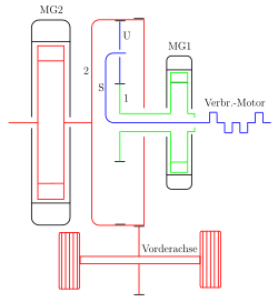
In the clutch-free hybrid drive (Toyota Prius, 1st generation) sketched schematically on the right, the combustion engine is connected to the web S and the smaller motor generator MG1 is connected to the sun gear. MG1 normally generates the charging current for the accumulator. At full load and high acceleration, the drive control MG1 switches to engine operation to support the internal combustion engine. Regardless of the internal gear state, the power of the large motor generator MG2, which acts directly on the drive axle, is added.
Another example is the drive of a ship's propeller by two motors via a summing gear.
Other applications have a motor that delivers great power at constant speed. With a smaller motor, the speed of which can be easily controlled, and a summing gearbox, a speed change at the output can be achieved in this way, for example in a rolling mill , in order to vary the speed during forming.
In aircraft construction , applications are known in which, for safety reasons, two electric motors drive a fuel pump via a summing gear. If one of the motors fails (stops), the other can still drive the pump at half speed.
Coupling and switching
The two-shaft operation is interrupted if the third shaft of the planetary gear is temporarily not held. This option is used as a general clutch or to shift gears in a gearbox.
Mainly in agricultural engineering there are clutches that can be switched under load and function in this way. For example, the PTO is switched on and off. The ring gear is firmly braked or left rotatable.
Classic automatic transmissions in motor vehicles have several epicyclic gears arranged one behind the other. To change gears, a different ratio is switched by opening and closing friction clutches and brakes. This is done as a power shift , there is no interruption of tractive effort.
Stepless speed change
With a continuously variable transmission, which in principle is not suitable for large powers, the speed of a rotary transmission provided with high power can be varied as follows (but with a reduced speed range): First, the rotary transmission is divided up with a planetary gear. A secondary branch with lower power is led via a continuously variable transmission to a second planetary gear, where it is then added up again with the power from the main branch of the first planetary gear.
A stepless hub gear
The continuously variable NuVinci gear hub is available for bicycles. This brand name contains the name of Leonardo da Vinci , who had already described the basic principle.
It is the well-known gear hub with a planetary gear, the gears of which ( form fit ) are replaced by friction wheels ( force or friction fit ) . The rotating gears have become rotating balls (ball gears). By pivoting their axes relative to the hub axis, the radii on which they have rolling contact with the driving and driven pulley (instead of the sun and ring gears) change. The infinitely variable swiveling means a stepless change in the gear ratio. In terms of kinematics, the NuVinci gear hub is an epicyclic gear with a variable positive stationary ratio.
The gear ratio spread (ratio of the largest to the smallest gear ratio) is 360% in the gear hub.
As in any frictional connection, the NuVinci gear hub can also slip and cause wear .
See also
literature
- Hugo Klein: The planetary epicyclic gears. Carl Hanser Verlag Munich, 1962.
- Fritz Winkler, Siegfried Rauch: Bicycle technology repair, construction, production. 10th edition, BVA Bielefelder Verlagsanstalt GmbH & Co. KG, Bielefeld, 1999, ISBN 3-87073-131-1 .
- Johannes Volmer: Gear technology epicyclic gears. Verlag Technik, Berlin, 1990.
Web links
- Epicyclic gears in automotive engineering at www.kfz-tech.de
- Relationship between planetary gears and differentials at www.arstechnica.de
Individual evidence
- ^ A b Siegfried Hildebrandt: Feinmechanische Bauelemente. Hanser, 1968, p. 542
- ↑ Equiaxed is meant in a geometric sense: The central or rotational axes are identical.
- ^ Siegfried Wetzel: Planetary gear on the bicycle. 5. Planetary gear in the rear hub of the Swissbee electric bicycle
- ↑ Johannes Looman, gear transmission, section 3.3.1.10 self-locking, Springer-Verlag Berlin Heidelberg, 3rd edition 2009, ISBN 978-3-540-89459-9
- ↑ Bernd Künne: Köhler / Rögnitz machine parts 2 . 10th edition. Vieweg + Teubner Verlag, 2008, ISBN 3-8351-0092-0 , p. 508 ( limited preview in Google Book search).
- ↑ Berthold Schlecht: Machine elements 2: gears, gears and bearings . 2nd Edition. Pearson Studium, 2010, ISBN 3-8273-7146-5 , pp. 787 ( limited preview in the Google book search - basic speed equation or Willis equation ).
- ↑ Eckhard Kirchner, power transmission in vehicle transmissions, see note 5.13, Springer-Verlag Berlin Heidelberg 2007, ISBN 978-3-540-35288-4
- ↑ Bernd Künne: Köhler / Rögnitz machine parts 2 . 10th edition. Vieweg + Teubner Verlag, 2008, ISBN 3-8351-0092-0 , p. 509 ( limited preview in Google Book search).
- ^ Image description Wikimedia Commons
- ^ Siegfried Wetzel: Planetary gear on the bicycle. 3. Planetary gear in hub gears
- ^ Siegfried Wetzel: Planetary gear on the bicycle. 4. Planetary gears in electric hub motors
- ^ Stiftung Warentest.de: NuVinci bicycle hub - shifting without gears. Retrieved August 8, 2012 .


